Prepared for: The U.S. Access Board
Prepared by:
U.S. Department of Transportation
Research and Innovative Technologies Administration
John A. Volpe National Transportation Systems Center
Cambridge, MassachusettsMichael G. Dyer

|
|
Abstract
Acknowledgements
Acronyms
Introduction
Approach
Risk Management Methodology
Application and examples
Summary and Actions
References
AppendicesRelated Document: Phase I: Background and History
This report examines a risk management methodology to provide for both marine safety and disability access at weathertight doors into passenger accommodation spaces on U.S. passenger vessels. The Architectural and Transportation Barriers Compliance Board’s ultimate objective is to assist designers and operators in improving disability access without compromising the vessel safety provisions of the coamings (sills) at these doorways. The methodology assigns numeric risk scores to several watertight integrity safety factors including door location and use, downflooding path, and vessel service. The aggregate risk score for a given door corresponds to a menu of possible access solutions. The methodology allows for the relocation of the door or other measures to lower the risk score and improve the access solution. The model is applied to several examples of doors on Subchapter T and K passenger boats.
The author wishes to thank the numerous organizations and individuals who graciously provided their time, knowledge and guidance in the development of this report. Our sponsors at the Architectural and Transportation Barriers Compliance Board have been supportive. We owe thanks to many in the U.S. Coast Guard who responded to our inquiries and contributed their time, their knowledge, and their experience. They include Captain Raymond Petow, Mr. Tom Jordan and Mr. Al Penn (Coast Guard Headquarters), LT Jason Hall and CWO4 Jim Hinde (Marine Safety Office, Boston), CWO Ray Rock (Marine Safety Office, Providence), and LCDR Tony Wiest (Marine Safety Center).
Several well-regarded naval architects contributed their knowledge and insight to review of the risk management methodology, affirming its credibility by a critical first review. Heartfelt gratitude is due Tim Graul of Timothy Graul Designs, John Hunter of Seaworthy Systems, and John Waterhouse of Elliott Bay Design Group. Pete Lauridsen of the Passenger Vessels Association (PVA) provided valuable technical guidance and was instrumental in setting up a peer review process by the PVA Partnership Action Team.
Finally, we must thank those who contributed the boat designs used as examples demonstrating application of the methodology. They were:
ADA - Americans with Disabilities Act, 1990
ADAAG - ADA Accessibility Guidelines for Buildings and Facilities (2002)
ATBCB - Architectural and Transportation Barriers Compliance Board
CFR - Code of Federal Regulations
COI - Certificate of Inspection
COTP -Captain of the Port
DOT - U.S. Department of Transportation
DF - Downflooding
ILLC -International Load Line Convention
IMO - International Maritime Organization
LLTM - Load Line Technical Manual
NVIC - Navigation and Vessel Inspection Circular
OCMI - Officer in Charge of Marine Inspection
PAT - Partnership Action Team
PAX - Passengers
PVA - Passengers Vessels Association
PVAAC - Passenger Vessel Access Advisory Committee
WL - Waterline
1.1 Background
The aim of this project is to find possible approaches to provide for both marine safety and disability access at doors into passenger accommodation spaces on U.S. passenger vessels. The sponsoring organization is the Architectural and Transportation Barriers Compliance Board (“the Board”, or ATBCB), an independent Federal agency, whose mission is to improve accessibility for people with disabilities. The Board’s objective was to assist designers, operators, and inspectors in improving disability access without compromising the vessel safety provisions of the coamings at weathertight doors, whose purpose is to prevent the entry of water into the passenger spaces served.
“Phase 1” preceded this report, and examined the following:
The focus of this study is on two of the smaller sized classes of regulated U.S. passenger vessels, known as Subchapter T and Subchapter K boats, named after the relevant sections in Title 46 (“Shipping”) of the Code of Federal Regulations (CFR). These boats generally are less than 100 gross tons and carry more than six passengers. T and K boats make up the overwhelming majority of passenger ferries and excursion vessels, such as dinner boats and whalewatchers, which are available to the general public.
1.2 Purpose
The purpose of Phase 2 was to develop new technical guidance and design solutions for weathertight doors meeting both the U.S. Coast Guard’s (“Coast Guard”) stability regulations and the Access Board’s accessibility design standards. The Access Board specified development of two types of access solutions:
1.3 Organization of Report
Chapter 2 describes the general approach to the problem. Chapter 3 presents the risk-based methodology in detail. Chapter 4 shows the results of applying the methodology to the reconfiguration of doors on three passenger boats. Chapter 5 is a summary of findings and recommendations.
2 Approach
It is useful at the outset to state the essential safety precepts in regard to watertight integrity, as expressed in national and international regulations and safety instruments. In the strict physical sense, the vessel consists of a watertight hull envelope and weathertight topside. The safety philosophy is to:
2.1 “Door design solution”
The primary goal of the Access Board was the door design solution, meaning proper independent access through any weathertight door used by passengers. The desired outcome was a design or designs of coaming-less doors where the marine safety inspector would otherwise specify a coaming. The initial consideration of such solutions in the Phase 1 report included conceptual alternate water barrier arrangements and alternate deck drainage arrangements.
The difficulty in seeking an engineering solution lies in the fact that the Coast Guard cannot quantify the hazard that coamings are meant to protect against, that is, the volumes, heights, and velocities of water on deck, and the frequency and duration of exposure. The watertight integrity and coaming regulations include no preamble and have no supporting analysis characterizing the hazard. Therefore, development, and approval, of “equivalent” alternate designs on the basis of first principles would be fraught with technical uncertainty.
The Coast Guard’s thinking on watertight integrity is grounded in the analogous regulations of the International Load Lines Convention, as expressed in the Load Line Technical Manual (USCG-M-1-90) and their regulations in 46 CFR, Subchapter E, Part 42. Doors and coamings are covered in the “conditions of assignment” (as described in the Phase 1 report), as are other topside structures, openings, and closures. Recent developments involving ocean-going ships covered by the Convention have tended towards strengthening conditions of assignment regulations rather than searching for alternate, equivalent solutions. The hazards addressed for such ships are likewise non-quantified, and the loss of many bulk carriers at sea, notably the Derbyshire, led to a re-examination and enhancement of regulations for the strength of closures, particularly cargo hatch covers.
These findings led to a decision to concentrate on the reconfiguration solution, rather than a pure engineering solution to a non-quantified problem.
2.2 “Reconfiguration solution”
The reconfiguration approach aims at access solutions by mitigating the hazard of water ingress and reducing risk, by protective placement of the door and minimization and control of water entry. The Phase 1 report showed in several cases that Coast Guard safety inspectors have de facto approved equivalences, based on common sense and without technical substantiation on the record. The risk management approach proposed here is a logical, risk-based guide to arrangement and design practice, building upon the ad hoc approaches developed in recent years among designers and Coast Guard inspectors. The outcome in past cases has been the elimination of coamings or the acceptance of other access designs based on several factors considered in an assessment of safety equivalency. This approach addresses manual doors only and does not include the access solutions suggested by the Passenger Vessel Access Advisory Committee (PVAAC).
The new approach assesses risk on a relative, quantitative scale, based upon several configuration and operations aspects. The results guide the designer to one or more intermediate design solutions or a finding that coamings must be included, as per the regulations. The intended result is a suggested solution or choice of solutions that must also be subject to sound judgment by the designer and safety inspector on a case-by-case basis.
The particulars of this approach are based upon several sources:
The Phase 1 work also revealed several ideas for intermediate access solutions, including doors with reduced height coamings and mitigating design features, such as removable coamings, double doors in sequence, and ADAAG-compliant short length ramps and platforms. These design features fit more aptly in the context of reconfiguration solutions, as improved doorway access options.
The main points of the risk-based approach are:
It is very important to properly characterize these risk-based guidelines as just that: a tool to be carefully applied, case by case, by the naval architect and the inspection authority, with sound technical judgment.
3.1 Terms of reference
The weathertight doors addressed herein are the following:
The reader should note that this methodology does not address interior doors, including fire zone doors, joiner doors, stairway access, and doors that are restricted to crew access. It may turn out, however, that this methodology can offer reconfiguration solutions that can be applied in these kinds of cases as well.
3.2 Characterization of risk factors
The proposed risk factors follow, with annotations showing the technical basis and supporting sources, for example, the Load Line Technical Manual or the Code of Federal Regulations:
CFR antecedents include the Subchapter S (“Stability”) regulation § 171.124 (“Watertight integrity above the margin line in a vessel less than 100 gross tons”) requires a coaming for an “exposed location on a flush deck vessel”. It requires interpretation by the designer and inspection authority to determine the extent to which the door’s location is “exposed”. In addition, Subchapters K (§ 114.400) and T (§ 175.400) both define “weather deck” in terms of exposure, specifying “partially or completely exposed from above or from at least two sides”.
This methodology also allows for lowering the risk score based upon protective design features within the space, that is, interior doors and coamings, drainage arrangements, or other structural barriers interdicting flow to the downflooding point(s). Distance between the weather deck door and the downflooding point is also a consideration in the model. Neither the Load Line Manual nor the CFR address these matters directly.
The downflooding paths may be generally categorized as follows:
- Direct access to space below the “bulkhead”, or main, deck, by an unprotected downflooding path, e.g., a stairway
- Indirect access to space below the bulkhead deck, that is, protective design features isolating the downflooding point(s)
- No access to lower deck
3.3 Numerical valuation of risk factors
The proposed risk categories and factors appear below, with numerical values in square brackets (i.e., subject to review and revision). Again, it is important to properly characterize the risk guidelines as just that: a guiding tool to be carefully applied, case by case, with sound technical judgment. The risk values appearing below increase in magnitude with increasing risk and are absolute pre-weighted numbers.
i. Purpose & use of door (scoring range: 0 - 2)
- [0] – Open only for embarkation/disembarkation, always closed during voyages
- [1] – Open during voyages for passenger access to weather deck, e.g., “promenade deck”
- [2] – Access to evacuation deck, required to be open in emergencies
ii. Door location (scoring range: 0 - 6)
Table 1. Door location risk scoring
Note: “Position 1” is between the bow and the point 0.25L aft of the bow;
“Position 2” is between the point 0.25L aft of the bow and the stern
Per definition of International Load Line Convention and the LLTM
| Height of deck at door < [8 feet] above waterline (WL) | Height of deck at door >/= [8 feet] above WL | |||
|---|---|---|---|---|
Position 1 |
Position 2 |
Position 1 |
Position 2 |
|
Facing outboard |
[2] |
[1] |
[1] |
[0] |
Facing aft |
[1] |
[2], if <0.25L from stern; [1], if >/= 0.25L from stern |
[0] |
[1], <0.25L from stern |
Facing forward |
[6] |
[4] |
[3] |
[2] |
ii. Downflooding Potential
- Downflooding (DF) path (scoring range: 0 - 6)
Table 2. Downflooding path risk scoring
X = distance from door to downflooding point
Y = height of downflooding point above deck
| X< [20 feet] | X>/= [20 feet] | |||
|---|---|---|---|---|
Y < [2 feet] |
Y >/= [2 feet] |
Y < [2 feet] |
Y >/= [2 feet] |
|
Manholes only |
[1] |
NA |
[0.5] |
NA |
Protected |
[2] |
[1] |
[1] |
[0] 4 |
Unprotected |
[6] |
[4] |
[4] |
[2] |
iv. Area of operation
The aggregate scores for the above risk categories should be multiplied as follows for the OCMI designation of waters (that is, for the purposes of the stability regulations) in which the vessel is authorized to operate.
Total scoring range
The range of possible aggregate scores (“R”), before multiplying for the area of operation, is 0 – 16. The range of possible aggregate scores, after multiplying for the area of operation, is 0 – 24.
3.4 Doorway access solutions
The final step in the process is to identify the potential access solutions indicated by the total risk scores. In application, a solution may be selected for any risk score in or below its designated range. A high aggregate risk score may indicate the need to relocate the door and/or incorporate more protective features, to lower the score and consider the selection of a door with improved access.
The proposed menu of solutions follows:
Examples:
- “Concept A” or B” exterior drains (see figures, Appendix A)
- Gladding – Hearn exterior drainage detail on Flying Cloud (Appendix B, Figure 3)
- Bulwarks, bulkheads, deck overhangs, etc. preventing passage of water to the door, especially from the direction of exposure, for example, from the bow for forward facing doors or from the stern for aft facing doors.
Aggregate risk score = [8 ? R ? 12]
This solution is for embarkation access only, that is, where the crew operates the door at known times and places only.
Aggregate risk score = [8 ? R ? 16]
Aggregate risk score = [16 ? R ? 20]
Aggregate risk score = [20 ? R ? 24]
3.5 Other doorway solutions
It may be fruitful to explore the possibilities for substitution of a watertight door with a minimally sized coaming, allowed in both the Subchapter T and K regulations (46 CFR 116.1160 and 179.360, respectively; see discussion, Phase 1 report). The currently available interpretation from Coast Guard safety personnel is that such substitution is meant specifically for vessels with licensed crew and other capable personnel (e.g., offshore drilling rig workers) aboard, who know how to operate a watertight door and can do so in emergency egress situations. This interpretation may be ripe for re-examination.
The use of such doors would raise other accessibility questions (hardware configuration and opening force); however, the result of the inquiry could be a set of new design requirements for consideration by watertight door manufacturers.
3.6 Embarkation doors at the deck edge
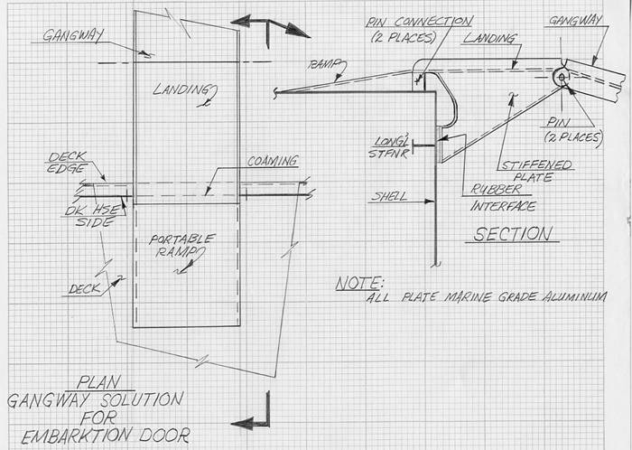
Many passenger boats have embarkation doors in the deckhouse side, at or very close to the deck edge and offering no weather deck access. Coamings are not the access barrier in these cases, but poorly designed gangways are. The problem most commonly seen is the double slope of the gangway and a short interior ramp meeting in an apex at the coaming (there are non-specification variations like the “whaleback” arching over the coaming). Gangways designed to provide proper slopes on both sides of the doorway and a proper landing over the coaming are the access solution, not removal or reduction of the coaming. A concept design appears in Appendix A, Figure 3.
The risk methodology was first exercised and tuned with examples of weathertight doors in the as-built condition (section 4.1). The next step was the development of reconfiguration cases on several representative, and recent, designs. Summaries of the reconfiguration cases appear in section 4.2, and the full texts appear in Appendices B through D.
4.1 As built cases
Table 3 shows a sampling of the results applying the risk scoring methodology to doors serving passenger accommodation spaces on existing boats. All the particulars and scoring factors for each door appear, as well as the aggregate risk score. Descriptions of the existing door and the access solution indicated by the methodology appear in the rightmost column, for the purpose of comparison.
The risk methodology indicates solutions that are for the most part similar to the existing as-built doors, particularly those cases where alternate arrangements were approved in the inspection process. The exceptions are among the doors examined on larger and older vessels, the Subchapter H and K boats. In these cases, the risk-based solutions were less conservative than the as-built doors.
In the case of the Subchapter K overnight excursion boat, the main deck door giving access to the stern has a 6” high coaming in strict accordance with the regulations. The location and downflooding potential result in a moderate aggregate risk score of 8.0, indicating the need for protection from water ingress but allowing for an alternate design for improved access. The risk score is on the cusp between designated ranges for three different solutions. The conservative choice would be a weathertight door with a reduced height coaming, with sloped deck ramp (grated for drainage) and landing at sill height.
An “01 level” (one deck above the main deck) door on the same vessel scored quite low for risk (aggregate = 3.5). The indicated solution is nearly identical to the as-built door and both provide good access.
The 01 level door on the Subchapter K casino boat has a 6” high coaming, but scores for moderate risk only (aggregate = 7.0). The indicated solution is a weathertight door with no coaming and drainage/ water barrier protection. A more conservative option would be a door with reduced height coaming [50%] with sloped deck ramp (grated) and a level landing at the coaming height.
The doors examined for Subchapter K and T passenger-only catamaran ferries of recent construction had low to moderate aggregate risk scores. Notably, the indicated solutions were very similar to the as-built doors in all three cases.
Table 3. Risk scoring for as-built door examples
| Pathway || To & From | Purpose and use of door ([0 – 2]) | Door Location ([0 – 6]) | DF Potential ([0 – 6]) | Size of space doorway leads to ([0 - 2]) | Area of Operation multiplier | Total risk ([0-24]) | Existing Door and Solution(s) |
|
|---|---|---|---|---|---|---|---|---|
| Subchapter K overnight excursion boat, weather deck | Passenger accomm. space | Passenger access to weather deck, alternate access not available (2) | Main deck, aft, facing stern; deck at door < 8’ above WL (2) |
Unprotected pathway to spaces below with 20’+ separation; Y < [2’] (4) |
Passage and passenger berths, less than 25% of main deck area (0) | Partially protected waters (1.0) | (2 + 2 + 4 + 0) * 1.0 = 8.0 | Existing door has 6” coaming. Indicated solutions are: 1) door with no coaming and protection for water; 2) door with removable regulation height coaming; or 3) reduced height coaming with sloped deck ramp (grated) and landing at sill height. 2 and 3 are the conservative choices. |
| Passenger accomm. space | Passenger access to weather deck, alternate access available (1) | 01 level, facing outboard, Pos. 1, less than 4’ from deck edge (1.5) | Protected pathway:20’+ separation; Y < [2’] (1) |
Passage and passenger berths, less than 25% of main deck area (0) | Partially protected waters (1.0) |
(1 + 1.5 + 1 + 0) * 1.0 = 3.5 | Existing sliding door has no coaming. Indicated solution is a weathertight door with no coaming. | |
| Subchapter K casino boat, forward weather deck | Passenger accomm. space | Passenger access to weather deck, no alternate access available, closed in bad weather (1) | 01 level, facing forward, Pos. 1, more than 8’ above waterline (3) | Protected pathway: 20’+ separation; Y < [2’] (2) |
Gaming room, 30% - 50% of main deck area (1) | Partially protected waters (1.0) | (1 + 3 + 2 + 1) * 1.0 = 7.0 | Existing double doors have 6” coaming and nearby deck drain. Indicated solution is a weathertight door with no coaming and drainage/ water barrier protection. |
| Subchapter H vehicle – passenger ferry, starboard weather deck | Passenger accomm. space | Passenger access to weather deck (1) | 02 level, facing outboard, within 4’ of deck edge (0) | No pathway to spaces below (0) | Passenger accomm. space, less than 25% of deck area (0) | Partially protected waters (1.0) | (1 + 0 + 0 + 0) * 1.0 = 1.0 | Existing door has 3” coaming with short ramps on either side. Indicated solution is a weathertight door with no coaming. |
| Subchapter K catamaran passenger ferry, starboard weather deck | Passenger accomm. space | Passenger access to weather deck (1) | Main deck aft, facing outboard, within 4’ of deck edge (1.5) | No pathway to spaces below (0) | Passenger accomm. space, more than 50% of main deck area (2) | Partially protected waters (1.0) | (1 + 1.5 + 0 + 2) * 1.0 = 4.5 | Existing sliding door has 1” coaming. Indicated solution is weathertight door with no coaming, with drainage or barrier protection. |
| Subchapter T catamaran passenger ferry, forward weather deck | Passenger accomm. space | Passenger embarkation, closed during operations (0) | Main deck Position 1, facing forward (6) | No pathway to spaces below (0) | Passenger accomm. space, more than 50% of main deck area (2) | Partially protected waters (1.0) | (0 + 6 + 0 + 2) * 1.0 = 8.0 | Existing double doors have no coaming with drainage in adjacent deck. Indicated solution is no coaming, with drainage or barrier protection. |
| Subchapter T catamaran passenger ferry, aft starboard weather deck | Passenger accomm. space | Passenger access to weather deck (1) | Main deck Position 2, facing outboard, within 4’ of shell (1.5) | No pathway to spaces below (0) | Passenger accomm. space, estimate more than 50% of main deck area (2) | Partially protected waters (1.0) | (1 + 1.5 + 0 + 2) * 1.0 = 4.5 | Existing sliding door has no coaming and protection of bulkheads forward. Indicated solution is weathertight door with no coaming, with drainage or barrier protection. |
4.2 Reconfiguration examples
Risk scoring tables appear for each case, but the door access solution is discussed in detail in the accompanying text rather than specified in the table (as was presented in 4.1).
4.2.1 Gladding – Hearn INCAT Designs, 35 meter long Subchapter T catamaran
This case study was to ascertain whether access through the forward doors for this bow-loading boat could be improved, possibly by the elimination of the coamings, on the basis of the risk management approach. The case was instructive because it uses a “type” boat design wherein a number of options for design and operation may be selected, allowing for examination of several scenarios involving design options and hypothetical consideration of operation in protected or partially protected waters. The design options were:
The design specifies weathertight doors, whether facing forward for bow loading, or aft for stern loading. Doors are presumed to have 3” coamings (designed per Subchapter S watertight integrity regulations for vessels less than 100 GT).
Tables 4 and 5 summarize the analytical framework for characterizing the design technical risk factors associated with the location and use of weathertight doors. The tables show four scenarios each for the forward and aft doors. Moving from the leftmost column rightward, the cells first divide to indicate the deck construction options, and then divide again for service in “protected” versus “partially protected” waters.
Table 4. 35-meter catamaran, risk scoring for forward door options
Pathway || To & From |
Purpose and use of door ([0 – 2]) |
Door Location ([0 – 9]) |
Downflooding Potential |
Area of Operation multiplier |
Total risk “R” ([0-24]) |
||
|---|---|---|---|---|---|---|---|
DF path ([0 – 6]) |
Size of space doorway leads to ([0 - 2]) |
||||||
Forward doors, port and starboard |
Weather |
Embark-ation only, closed otherwise |
Door sill less than [8 feet] above WL, facing forward in Position 2 (4.0) |
Manholes only (1.0) |
Passenger accomm. space, more than 50% of main deck area (2.0) |
Protected waters (0.75) |
(0 + 4 + 1 + 2) * 0.75 = 5.25 |
Partially protected waters (1.0) |
(0 + 4 + 1 + 2) * 1.0 = 7.0 |
||||||
“Floating” deck, no DF pathway (0.0) |
Protected waters (0.75) |
(0 + 4 + 0 + 2) * 0.75 = 4.5 |
|||||
Partially protected waters (1.0) |
(0 + 4 + 0 + 2) * 1.0 = 6.0 |
||||||
Based strictly upon the aggregate risk scores, the aft doors would appear to be the better choice for passenger access. The scores in both cases are low, however, and an accessible pathway via the bow doors would also be appropriate for the right combination of design features and operation. Note that access through the aft doors to the aft weather deck is required whether or not the embarkation pathway includes those doors.
Forward doors
In the bow loader configuration with forward embarkation doors, the choice of a “floating” deck would reduce the risk scores from 5.25 and 7.0 to 4.5 and 6.0, for service in protected and partially protected waters, respectively. The benefit of the floating deck for either service choice is modest and does not substantively change the outcome, because the downflooding risk from the closed manholes in the passenger cabin is low to start with.
With or without the floating deck, in protected water service, the solution would be a coaming-less weathertight door. The risk for this design could be further reduced with protective drainage features against water on deck. It may be appropriate to replace the weathertight door with coaming with an improved access doorway, for example, a weathertight door with a coaming of reduced height, and protective drainage.
Table 5. 35-meter catamaran, risk scoring for aft door options
Pathway || To & From |
Purpose and use of door ([0 – 2]) |
Door Location ([0 – 9]) |
Downflooding Potential |
Area of Operation multiplier |
Total risk “R” ([0-24]) |
||
|---|---|---|---|---|---|---|---|
DF path ([0 – 6]) |
Size of space doorway leads to ([0 - 2]) |
||||||
Aft doors, port and starboard |
Weather |
Embark-ation, and passenger access to weather deck during voyage |
Door sill less than [8 feet] above WL, facing aft in Position 2 (1.0) |
Manholes only (1.0) |
PAX accomm. space, more than 50% of main deck area (2.0) |
Protected waters (0.75) |
(1 + 1 + 1 + 2) * 0.75 = 3.75 |
Partially protected waters (1.0) |
(1 + 1 + 1 + 2) * 1.0 = 5.0 |
||||||
“Floating” deck, no DF pathway (0.0) |
Protected waters (0.75) |
(1 + 1 + 0 + 2) * 0.75 = 3.0 |
|||||
Partially protected waters (1.0) |
(1 + 1 + 0 + 2) * 1.0 = 4.0 |
||||||
Aft doors
Use of the aft doors for access to the weather deck is required whichever embarkation path is chosen. The floating deck results in scores of 3.0 and 4.0 for the protected and partially protected waters. A coaming-less door would be appropriate in either case. For partially protected waters, the score of 4.0 is on the cusp and it might be appropriate to include protective drainage or a reduced height coaming with ADA-compliant short ramps on either side.
Without the floating deck, the aggregate risk scores rise slightly. Protective drainage or a reduced height coaming with short ramps and a landing would be appropriate for service in partially protected waters.
Discussion
It is evident that the door location and the large size of the accommodation space drive the aggregate risk score in all the scenarios, especially for the forward doors. The floating deck eliminates downflooding paths, but the benefit is modest because the only potential downflooding points in this case are bolted manhole covers leading to tanks and voids; the likelihood of any of those manholes being open during a voyage is slight. It turned out that the scoring bandwidth for all scenarios was relatively narrow at the low risk end of the range, but that there are several possible solutions.
This case shows there may be several design, operations, and economics decision points, of which mobility access is one. The operator and builder can consider accessible paths onboard in overall context of the desired operation for the boat (market served, waters served, and shoreside infrastructure and loading mode), and the added cost of mitigative safety features. An accessible pathway through either the forward or aft doors is feasible, given different design and operational choices.
4.2.2 Casco Bay Line monohull passenger only ferry, Subchapter K, 399 passengers, protected waters service
In this case, embarkation is via sliding weathertight doors on the main deck, port and starboard, forward (approximately 0.25L from the bow) at the deck edge. The doors have 3” coamings (per Subchapter S). The risk model exercise is to ascertain whether the coamings could be eliminated to improve embarkation access and simplify the design of the gangways from the shoreside piers.
Discussion
The embarkation doors, as designed, scored 4.5. The indication is that a weathertight door without coaming might be suitable. However, there would be no exterior drainage or water barrier protection available, given the deck edge location. The conservative approach would dictate retention of the coaming as structural protection and a strong gasketing surface against the unlikely event of waves impinging on the door.
Two possible reconfigurations would lower the risk score to below 4.0 and allow installation of a no coaming weathertight sliding door. First, the doors could remain in their forward position in a 48” recess, a protective bulkhead forward, and possibly a portable protective coaming at the deck edge while the door is closed. As shown in Table 6, the overall risk score would be 3.75 and the solution would be a sliding weathertight door with no coaming, with limited impact on the internal arrangement.
The second approach would be to move the doors aft to approximately amidships, resulting in a lowered aggregate risk score of 3.4 and a sliding coaming-less door. The internal space arrangement modification would be minimal. Bench space lost amidships would be regained forward at the former position of the door.
In this case, the two “downflooding” sub-factors, “distance to downflooding point” and “area of accommodation space”, work against each other. Long distances to the downflooding point are more common in large accommodation spaces. At first blush, it seems that rethinking this contradictory linkage is necessary. However, the space area metric also protects against large volumes of entrapped water, should the worst situation occur, that is, a failed door allowing ingress of large amounts of water from waves abeam or heavy spray.
Table 6. Subchapter K monohull ferry, risk scoring for embarkation door options
Pathway || To & From |
Purpose and use of door ([0 – 2]) |
Door Location ([0 – 9]) |
Downflooding Potential |
Area of Operation multiplier |
Total risk “R” ([0-24]) |
||
|---|---|---|---|---|---|---|---|
DF path ([0 – 6]) |
Size of space doorway leads to ([0 - 3]) |
||||||
As defined configuration |
|||||||
Forward embarkation doors, port and starboard, as designed |
PAX accomm. space |
Embarkation only, closed otherwise |
Less than [8 feet] above waterline, on deck edge, facing outboard in Position 1 (2.0 X 1.5 = 3.0) |
Protected DF pathway: DF point at least [20 feet] from the door; Y < [2 feet] |
More than 50% of main deck area (2.0) |
Protected waters (0.75) |
(0 + 3 + 1 + 2) * 0.75 = 4.5 |
Reconfigurations |
|||||||
Forward embarkation doors, port and starboard, recessed inboard |
PAX accomm. space |
Embarkation only, closed otherwise |
Door sill less than [8 feet] above the main deck, inboard of deck edge, facing outboard in Position 1 (2.0) |
Protected DF pathway; DF point at least [20 feet] from the door; Y < [2 feet] |
More than 50% of main deck area (2.0) |
Protected waters (0.75) |
(0 + 2 + 1 + 2) * 0.75 = 3.75 |
Amidship embarkation doors, port and starboard, at deck edge |
PAX accomm. space |
Embarkation only, closed otherwise |
Door sill less than [8 feet] above main deck, on deck edge, facing outboard in Position 2 (1.0 X 1.5 = 1.5) |
Protected DF pathway; DF point at least [20 feet] from the door; Y < [2 feet] |
More than 50% of main deck area (2.0) |
Protected waters (0.75) |
(0 + 1.5 + 1 + 2) * 0.75 = 3.4 |
4.2.3 Graul monohull dinner boat, Subchapter K, 127’ long, 368 passengers, protected or partially protected waters service
This is to ascertain whether the coamings could be eliminated or reduced on a risk management basis. The main deck passenger cabin has weathertight doors with 6” coamings, forward for weather deck access, and aft for embarkation and weather deck access. In this case, the reconfiguration will be to better protect downflooding points.
Table 7. Subchapter K dinner boat, risk scoring for embarkation door options
Pathway || To & From |
Purpose and use of door ([0 – 2]) |
Door Location ([0 – 9]) |
Downflooding Potential |
Area of Operation multiplier |
Total risk “R” ([0-24]) |
||
|---|---|---|---|---|---|---|---|
DF path ([0 – 6]) |
Size of space doorway leads to ([0 - 3]) |
||||||
As defined configuration |
|||||||
Forward weather deck door |
PAX cabin |
Weather deck access and embark-ation |
Door sill less than [8’] above WL, facing forward, in Position 2 (4) |
Unprotected pathway, separation of DF point more than [20 feet] from the door, less than [2 feet] above the deck. (4) |
|
Protected waters (0.75) |
(1 + 4 + 4 + 2) * 0.75 = 11 * 0.75 =8.25 |
Partially protected waters (1.0) |
11.0 * 1.0 = 11.0 |
||||||
Aft weather deck door |
PAX cabin |
Ditto |
Door sill less than [8’] above WL, facing aft, < 0.25L from stern, with struct. protection from water (1.33) |
Ditto, except DF point is less than [20 feet] from the door |
Ditto |
Protected waters (0.75) |
(1 + 1.33 + 6 + 2) * 0.75 = 10.3 * 0.75 = 7.75 |
Partially protected waters (1.0) |
10.3 * 1.0 = 10.3 |
||||||
Reconfigurations |
|||||||
Forward weather deck door |
Ditto above |
Ditto above |
Ditto above |
Protected DF path, same horiz./vert. separations (1.0) |
Ditto above |
Protected (0.75) |
6.0 |
Part. Prot. (1.0) |
8.0 |
||||||
Aft weather deck door |
Ditto above |
Ditto above |
Ditto above |
Ditto (2.0) |
Ditto above |
Protected (0.75) |
4.75 |
Part. Prot. (1.0) |
6.3 |
||||||
The aggregate risk scores in Table 7 indicate that some form of weathertight protection is appropriate both for forward and aft doors, especially for partially protected waters service, for which the doors are designed. The deck arrangement precludes relocation or reconfiguration of the doors without serious impact. The reasonable approach is to examine reconfiguration of other risk elements, and the best accessible pathway.
The best way to reduce risk is better protection of the downflooding point. Replacing the non-weathertight door at the downflooding point with a weathertight door with a coaming would significantly reduce the risk. The downflooding path score for both the forward and aft doors would drop from 4 to 1 and from 6 to 2, respectively, as per Table 8.
Table 8. Downflooding paths, Graul dinner boat, revised scores
Note: Asterisk(*) used to highlight table provisions which apply to the dinner boat after reconfiguration
Risk scores for downflooding path |
X< [20 feet] |
X>/= [20 feet] |
||
|---|---|---|---|---|
Y < [2 feet] |
Y >/= [2 feet] |
Y < [2 feet] |
Y >/= [2 feet] |
|
Manholes only |
[1] |
NA |
[0.5] |
NA |
Protected |
*Aft door: [2] |
[1] |
*Forward door: [1] |
[0] |
Unprotected |
* |
[4] |
* |
[2] |
The aggregate risk scores for the aft door drop considerably, and a weathertight, accessible coaming-less door aft with a protective drainage arrangement appears to be appropriate for both protected waters and partially protected waters service.
The forward door has significantly lowered scores, but remains in need of protection against water entry. The conservative approach for safety might dictate retention of at least a reduced height (3”) coaming and designation of the aft door only as accessible for the mobility-impaired. This would provide the embarkation pathway and the accommodation of access to the weather deck. The fore deck would remain available to other passengers for embarkation and access during voyages. There would be benefit to the operator here as well in the reduction of the barrier for able-bodied passengers.
5.1 Findings
5.2 Course of Action
The Passenger Vessels Association (PVA) and the Coast Guard’s "Partnership Action Team" (PAT) expressed support for the risk methodology at its January 2005 meeting, and agreed to undertake a formal peer review process, offering technical and operational insights to improve the tool. The PAT intends to put the risk methodology reports into the current Department of Transportation (DOT) docket for the rulemaking “Nondiscrimination on the Basis of Disability: Passenger Vessels”, docket number OST-2004-19700. At the time of this report’s completion, the PAT had agreed to prepare a charter identifying the course of action and had asked PVA members to help by providing:
5.3 Issues
There are several significant questions at the time of this report’s completion. The first concerns the technical particulars as they may be affected by the future PAT review and the public’s response after the report is placed in the DOT docket.
The second question is the eventual disposition of the risk-based methodology. The Coast Guard, industry, and the author agree that it should not become part of the Coast Guard’s or the Access Board’s regulations. One possible outcome is its publication as a Coast Guard “Navigation and Vessel Inspection Circular” (NVIC). NVICs function as technical guidance to industry and have proven a very useful tool for many safety and environmental protection matters in the past.
Finally, there is a set of questions concerning the prospective designs of weathertight and watertight doors providing enhanced access, that is, in conjunction with reduced height coamings and short ramps. These address the enhanced access solutions offered in the risk-based methodology and the extent to which marine door manufacturers can respond to the need for accessible doors. The questions are:
Access for Persons with Disabilities to Passenger Vessels and Shore Facilities, The Impact of the Americans with Disabilities Act of 1990, prepared by the Volpe National Transportation Systems Center for the Office of Secretary of Transportation, July 1996
Americans with Disabilities Act Accessibility Guidelines, United States Access Board, 2002
Coast Guard Maine Safety Manual Chapter 3: Documentation of Vessel Inspections.
Code of Federal Regulations, Title 46 “Shipping”, Subchapters C, H, K, S, and T
Passenger Vessel Access Advisory Committee, “Recommendations for Accessibility Guidelines for Passenger Vessels: Final Report”, December 2000.
Appendix A - Figures
Appendix B - Numerical risk evaluation, main deck doors, 35 meter long catamaran 149 passengers
Gladding-Hearn Shipbuilding and INCAT Designs - Sydney
Appendix C - Numerical risk evaluation, main deck doors, 399 passenger ferry, Casco Bay Line
Appendix D - Numerical risk evaluation, main deck doors, 127’/368 Passenger Dinner Boat, Graul Desig
FIGURE 1. SUMP AND DRAIN ADJACENT TO THE DOOR

FIGURE 2. DRAINAGE SLUICES ADJACENT TO THE DOOR

FIGURE 3. GANGWAY SOLUTION FOR EMBARKATION DOOR
Numerical risk evaluation, main deck doors
35 meter long catamaran 149 passengers
Gladding-Hearn Shipbuilding and INCAT Designs - Sydney
INTRODUCTION
This paper shows an application of the proposed use of risk indices leading to enhanced doorway access solutions for people with mobility impairments. It is important to note that the risk guidelines are to be carefully applied, on a case by case basis, with sound technical judgment.
The particulars of the case for this Gladding-Hearn and INCAT Designs (GH-ICD) boat (deck plan, Figure 1) are:
This case study is to ascertain whether access through the doors could be improved, possibly by the elimination of the coamings, on the basis of the risk management approach. This example is instructive because it uses a “type” boat design wherein a number of options for design and operation may be selected. This allows for examination of several scenarios involving the two design options shown above, deck structure types and bow vs. stern embarkation. The study includes hypothetical consideration of operation in partially protected waters as well, recognizing that the builder intends the design for protected water operations.
Figure 1. General plans, Gladding –Hearn/INCAT 35 meter catamaran

Figure 2. Gladding-Hearn INCAT Design boats 331 and 332 at dock.
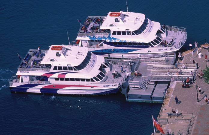
NOTE: These boats are not identical to the design chosen for this example and shown in Figure 1. The photograph shows how bow doors and bow loading reconfigure the design (boat at bottom of photograph) of the passenger cabin. The configuration of the side loader (at top) has different doors into aft area of the passenger cabin, which are not part of the configuration for this example, as shown in Figure 1.
APPLICATION
The descriptive language for the risk factors developed in the Volpe Center report appears verbatim. The risk values appearing below increase in magnitude with increasing risk and are absolute un-weighted numbers.
The forward doors and aft doors are treated separately (sub-headings i and ii), each with scenarios for the two deck construction techniques. Gray text shading of text show the particulars for the subject case, with annotations added where appropriate. Annotations show differences between the cases of the separate floating deck and the structurally integral deck..
The risk summation for all scenarios follows the detailed scoring for the forward and aft doors, appearing in Table 5, and with a discussion of possible doorway access solutions.
Note: Asterisk (*) inidcates those provisions which apply to GH/INCAT vessel where more than one provision is listed.
1. FORWARD DOORS
i. Purpose & use of door
- *[0] – Open only for embarkation/disembarkation, always closed during voyages. NOTE: GH-ICB state that there is no passenger access to the forward weather deck during voyages.
- [1] – Open during voyages for passenger access to weather deck, e.g., “promenade deck”, alternate access available
- [2] – Access to evacuation deck, required to be open in emergencies
ii. Door location
Note: “Position 1” is between the bow and the point 0.25L aft of the bow;
“Position 2” is between the point 0.25L aft of the bow and the stern
Per definition of International Load Line Convention and the LL Technical Manual
| Risk scores for door position | Sill < 8 feet above WL | Sill >/= [8 feet] above WL | ||
|---|---|---|---|---|
Position 1 |
Position 2 |
Position 1 |
Position 2 |
|
Facing outboard |
[2] |
[1] |
[1] |
[0] |
Facing aft |
[1] |
[2], if < 0.25L from stern; [1], if >/= 0.25L |
[0] |
[1], <0.25L from stern |
*Facing forward |
[6] |
*[4] |
[3] |
[2] |
*Note: For the GH/INCAT, there is no reduction credited here because the protective features forward of the door are relatively short in height and are about 8 meters away.
iii. Downflooding potential
- Downflooding path
The plan provided shows no downflooding path in the passenger accommodation space. Manholes giving access to engine room spaces appear aft of the deckhouse on the weather deck. The engine rooms’ air supply plenums (frames 9 – 10, port and starboard) are in the aft corners of the passenger accommodation space; the intake ducts would be in the aft or outboard bulkheads of the plenum, NOT in the passenger space. However, it is assumed that there are bolted manhole covers elsewhere in the space giving access to fuel tanks and void spaces. The conservative view would be that there is a “protected” downflooding path in the space for integral deck construction. Such is not the case for the “floating” deck construction, where there is no downflooding path.
| Risk scores for downflooding path | X< [20 feet] | X>/= [20 feet] | ||
|---|---|---|---|---|
Y < [2 feet] |
Y >/= [2 feet] |
Y < [2 feet] |
Y >/= [2 feet] |
|
Manholes only |
*[1], structurally integrated deck |
NA |
[0.5] |
NA |
Protected |
[2] |
[1] |
[1] |
[0] |
Unprotected |
[6] |
[4] |
[4] |
[2] |
- *[0] – no pathway of any kind to watertight spaces below the passenger deck, for “floating deck”
- Manholes only. Watertight, bolted, flush manholes leading to void spaces, tanks, and unmanned spaces, closed during voyages.
- Protected: Watertight or weathertight closures (doors or hatchways) with coaming at downflooding point(s)
- Unprotected: Joiner doors, ventilation openings to spaces below
- X = distance from door to downflooding point
- Y = height of downflooding point above deck
iv. Area of operationThe aggregate scores for the above risk categories should be multiplied as follows for the OCMI designation of waters (that is, for the purposes of the stability regulations) in which the vessel is authorized to operate.
- * Protected :: [0.75]
- *Partially protected :: [1.0] (both areas of operation considered)
- Exposed :: [1.5]
2. AFT DOORS
i. Purpose & use of door
- [1] – Open during voyages for passenger access to weather deck, e.g., “promenade deck”, alternate access available. NOTE: Access through these doors to the aft weather deck is required whether the forward or aft doors are the chosen embarkation path.
ii. Door location
Note: “Position 1” is between the bow and the point 0.25L aft of the bow;
“Position 2” is between the point 0.25L aft of the bow and the stern
(Per definition of International Load Line Convention and the Load Line Technical Manual)
Risk scores for door position |
Sill < 8 feet above WL |
Sill >/= [8 feet] above WL |
||
|---|---|---|---|---|
|
Position 1 |
Position 2 |
Position 1 |
Position 2 |
Facing aft |
[1] |
[2], if < 0.25L from stern; |
[0] |
[1], <0.25L from stern |
For doors with low exterior exposure to the elements due to protective structural elements, multiply score by [0.67]. *NOTE: For the GH/INCAT vessel, there is no reduction credited here because there are very limited protective structural features nearby.
iii. Downflooding potential
- Downflooding path
*See discussion for forward doors. Score is 1.0.
- Size of accommodation space that the doorway leads to
- * [2.0] – more than [50%] of main deck area
iv. Area of operation
- * Protected ::[0.75]
- *Partially proected ::[1.0]
3. Risk summary and solutions
Table 1 summarizes the analytical framework for characterizing the design technical risk factors associated with the location and use of weathertight doors. The first two columns describe the pathway served by the door, and its purpose and operational function. The next four are individual risk factors, which are to be scored as specified above, with ranges defined by relative severity of the hazard. Aggregated risk scores are in the seventh column.
The table shows four scenarios for both the forward and aft doors. Moving from the leftmost column rightward, the cells first divide to indicate the deck construction options, and then divide again for service in “protected” versus “partially protected” waters.
Table 1 (forward doors)
Pathway || To & From |
Purpose and use of door ([0 – 2]) |
Door Location ([0 – 9]) |
Downflooding Potential |
Area of Operation multiplier |
Total risk “R” ([0-30]) |
Solution(s) |
||
|---|---|---|---|---|---|---|---|---|
DF path ([0 – 6]) |
Size of space doorway leads to ([0 - 2]) |
|||||||
Forward doors |
||||||||
Forward doors, port and starboard |
Weather || passenger accomm. space |
Embarkation only, closed otherwise |
Door sill less than [8 feet] above WL, facing forward in Position 2 (4.0) |
Manholes only (1.0) |
Passenger accomm. space, more than 50% of main deck area (2.0) |
Protected waters (0.75) |
(0 + 4 + 1 + 2) * 0.75 = 5.25 |
Passenger embarkation only for a “bow loader”: The 4 scores are in the low range. “Floating” deck yields modestly lower risk scores because of DF through manholes is low risk. Additional protective features against water on deck would improve the case for an accessible doorway solution, especially for partially protected water service. |
Partially protected waters |
(1.0) |
|||||||
“Floating” deck, no DF pathway (0.0) |
Protected waters (0.75) |
(0 + 4 + 0 + 2) * 0.75 = 4.5 |
||||||
Partially protected waters |
(1.0) |
|||||||
Aft doors |
||||||||
Aft doors, port and starboard |
Weather || passenger accomm. space |
Embarkation and passenger access to weather deck during voyage |
Door sill less than [8 feet] above WL, facing aft in Position 2 (1.0) |
Manholes only (1.0) |
Passenger accomm. space, more than 50% of main deck area (2.0) |
Protected waters (0.75) |
(1 + 1 + 1 + 2) * 0.75 = 3.75 |
Accessible embarkation and deck access via the aft doors are appropriate for all scenarios. The low scores in protected waters indicate that with or without a “floating” deck a coaming-less door would be appropriate. For service in partially protected waters, scores are low as well. Without the floating deck, more protection would be needed for an accessible door solution. |
Partially protected waters (1.0) |
(1 + 1 + 1 + 2) * 1.0 = 5.0 |
|||||||
“Floating” deck, no DF pathway (0.0) |
Protected waters (0.75) |
(1 + 1 + 0 + 2) * 0.75 = 3.0 |
||||||
Partially protected waters |
(1.0) |
|||||||
Doorway Solutions
The roster of possible access enhancement solutions appears below, tied to sub-ranges of total risk scores as shown:
NOTE: Subchapters K and T (46 CFR 116.1160 and 179.360, respectively) allow for substituting a watertight door with a minimal height sill for a weathertight door with a coaming. Such would be appropriate for a door with any risk score, if operation of the door is by crew only (as currently interpreted by Coast Guard) as for use in embarkation/disembarkation only, or if industry develops a watertight door appropriate for operation by passengers.
Based strictly upon the risk scores, the aft doors would appear to be the better choice for passenger access. The scores in both cases are low, however, and an accessible pathway via the bow doors would also be appropriate for the right combination of design features and operation. Note that access through the aft doors to the aft weather deck is required wherever the embarkation point and pathway are sited.
Forward doors
If the desired configuration were a “bow loader” with the forward deckhouse doors used for embarkation only, the choice of a “floating” deck would reduce the risk scores by 0.75 and 1.0 to 4.5 and 6.0, for protected and partially protected waters, respectively. The benefit is modest and does not substantively change the outcome, because the downflooding risk from the closed manholes in the passenger cabin is low to start with.
With or without the floating deck, in protected water service, the solution indicated would be a coaming-less weathertight door (possibly similar to the GH-ICB sliding doors found on the Flying Cloud) or a watertight door with minimal height sill, as allowed by the CFR for operation by able-bodied crew. The risk for this design could be further reduced with protective drainage features against water on deck (e.g., the GH-ICB drainage detail for Flying Cloud, Figure 3).
Similarly for partially protected water service, the risk reduction due to the floating deck does not significantly change the outcome. It may be appropriate to replace the weathertight door with coaming with an improved access doorway, for example, a weathertight door with a coaming of reduced height, and the Flying Cloud drainage detail. Addition of protective structure forward of the door (against water on deck) to reduce the risk appears infeasible because of the access route from bow doors to the deckhouse.
In this example case, the operator and builder would have to consider accessible paths onboard in overall context of the desired operation for the boat (market served, waters served, and shoreside infrastructure and loading mode), the added cost of the floating deck and drainage features. An accessible pathway through the forward doors appears to be feasible, given the correct operational procedures and protective features forward of the doors.
Alternatively, the desired approach in this case may be retaining the forward weathertight doors as designed and providing passenger access via the aft bulwark gates and aft deckhouse doors. In this scenario, the boat would be configured for aft loading and the forward doors would be for crew only access. An improved access doorway could still be installed for future operational flexibility, or the conservative approach taken, that is, a weathertight door with 3” coaming, as designed.
Aft doors
Use of the aft doors for access to the weather deck is required whichever embarkation path is chosen. The floating deck results in scores of 3.0 and 4.0 for the protected and partially protected waters. A coaming-less door would be appropriate in either case, possibly similar to the aft sliding doors on the Flying Cloud. For partially protected waters, the score of 5.0 is on the cusp and it might be appropriate to include a protective drainage feature to be on the safe side or a reduced height coaming with ADA-compliant short ramps on either side.
Without the floating deck, the protective drainage feature or a reduced height coaming with ADA-compliant short ramps on either side would be appropriate, especially for partially protected waters.
Scoring methodology comments
The case shows how the builder and operator may have several design and operations decision points in which mobility access is one element in the consideration of cost. In this case, it turns out that the scoring bandwidth for all scenarios is relatively narrow at the low risk end of the range, but that there are several possible solutions.
As for the particulars of the scoring, it is evident that the door location and the size of the accommodation space drive the aggregate score in all scenarios, especially for the forward doors. The floating deck eliminates downflooding paths, but the benefit is modest because the only potential downflooding points in this case are bolted manhole covers leading to tanks and voids; the likelihood of any of those manholes being open during a voyage is slight. The scoring methodology now includes an added field “bolted manholes closed during voyages”, scored as [1.0] in this case study. The risk is lower than for a tight door leading to a workspace below but does not equate to the “no pathway” score of [0].
The exposure of the forward doors and the size of the passenger space alone raise the risk score above the lowest category, even for protected water service. The hazard of the forward door location is clear in the science and the regulations. The affected space area metric may bear more scrutiny, but the idea is that it protects against large volumes of entrapped water, should the worst situation occur, that is, a failed door allowing ingress of large amounts of water from waves or heavy spray.
FIGURE 3. DRAINAGE DETAIL, GH-ICB BOAT FLYING CLOUD, FORWARD EMBARKATION DOORS

Numerical risk evaluation, main deck doors,
399 passenger ferry, Casco Bay Line
INTRODUCTION
This paper shows an application of the proposed use of risk indices leading to enhanced doorway access solutions for people with mobility impairments. It is important to note that the risk guidelines are to be carefully applied, on a case by case basis, with sound technical judgment.
The risk values appearing below increase in magnitude with increasing risk and are absolute pre-weighted numbers. The particulars of the case are:
APPLICATION
The descriptive language for the risk factors appears verbatim, with gray shading showing the particulars for the subject case and annotations where needed. The risk summation appears in Table 1, followed by a discussion of the possible solutions.
Note: Asterisk (*) indicates those provisions which apply to the ferry where more than one provision is listed.
i. Purpose & use of door
- *[0] – Open only for embarkation/disembarkation, always closed during voyages
- [1] – Open during voyages for passenger access to weather deck, e.g., “promenade deck”, alternate access available
- [2] – Access to evacuation deck, required to be open in emergencies
Figure 1. Casco Bay Line boat – Profile

Figure 2. Casco Bay Line boat – Main Deck Plan

ii. Door location
Note: “Position 1” is between the bow and the point 0.25L aft of the bow;
“Position 2” is between the point 0.25L aft of the bow and the stern
Per definition of International Load Line Convention and the Load Line Technical Manual
Risk scores for door position |
Sill < 8 feet above WL |
Sill >/= [8 feet] above WL |
||
|---|---|---|---|---|
|
Position 1 |
Position 2 |
Position 1 |
Position 2 |
Facing outboard |
*[2] X [1.5] |
|
[1] |
[0] |
- *For doors facing outboard, multiply score by [1.5] if the door is within [4 feet] of the deck edge.
- For doors with low exterior exposure to the elements due to protective structural elements, multiply score by [0.67].
*NOTE: For Casco Bay Line board, doors are at 0.25L point. The Position 1 score is assigned as the conservative choice.
iii. Downflooding potential
- Downflooding path to lower deck spaces
Risk scores for downflooding path |
X< [20 feet] |
X>/= [20 feet] |
||
|---|---|---|---|---|
Y < [2 feet] |
Y >/= [2 feet] |
Y < [2 feet] |
Y >/= [2 feet] |
|
Manholes only |
[1] |
NA |
[0.5] |
NA |
Protected |
[2] |
[1] |
*[1] |
[0] |
Unprotected |
[6] |
[4] |
[4] |
[2] |
- [0] – no pathway of any kind to watertight spaces below the passenger deck
- Manholes only. Watertight, bolted, flush manholes leading to void spaces, tanks, and unmanned spaces, closed during voyages.
- Protected: Watertight or weathertight closures (doors or hatchways) with coaming at downflooding point(s)
- Unprotected: Joiner doors, ventilation openings to spaces below
- X = distance from door to downflooding point
- Y = height of downflooding point above deck
- Size of accommodation space that the doorway leads to
- [0] – less than [25%] of main deck area
- [1] – between [25%] and [50%] of main deck area
- *[2] – more than [50%] of main deck area
iv. Area of operation
The aggregate scores for the above risk categories should be multiplied as follows for the OCMI designation of waters (that is, for the purposes of the stability regulations) in which the vessel is authorized to operate.
- *Protected :: [0.75]
- Partially protected :: [1.0]
- Exposed :: [1.5]
Table 1 summarizes the analytical framework for characterizing the design technical risk factors associated with the location and use of weathertight doors. The first two columns describe the pathway served by the door, and its purpose and operational function. The next four are individual risk factors, which are to be scored as specified above, with ranges defined by relative severity of the hazard.
Table 1’s first row shows the door as designed, in its forward position at the deck edge. The second and third rows show the scoring for alternate door arrangements. Discussion of the solutions for these cases appear following Table 1.
Table 1
Pathway || To & From |
Purpose and use of door ([0 – 2]) |
Door Location ([0 – 9]) |
Downflooding Potential |
Area of Operation multiplier |
Total risk “R” ([0-30]) |
Solution(s) |
||
|---|---|---|---|---|---|---|---|---|
DF path ([0 – 6]) |
Size of space doorway leads to ([0 - 3]) |
|||||||
Current configuration |
||||||||
Forward embarkation doors, port and starboard, as designed |
Passenger accomm. space |
Embarkation only, closed otherwise |
Door sill less than [8 feet] above the main deck, on deck edge, facing outboard in Position 1 (2.0 X 1.5 = 3.0) |
Protected DF pathway; separation of downflooding point of at least [20 feet] from the door (1.0)
|
Passenger accommodation space, more than 50% of main deck area (2.0) |
Protected waters (0.75) |
(0 + 3 + 1 + 2) * 0.75 = 4.5 |
Conservative approach: door with 3” coaming, as designed. |
Reconfigurations |
||||||||
Forward embarkation doors, port and starboard, recessed inboard |
Passenger accomm. Space |
Embarkation only, closed otherwise |
Door sill less than [8 feet] above the main deck, inboard of deck edge, facing outboard in Position 1 (2.0) |
Protected DF pathway; separation of downflooding point of at least [20 feet] from the door (1.0)
|
Passenger accommodation space, more than 50% of main deck area (2.0) |
Protected waters (0.75) |
(0 + 2 + 1 + 2) * 0.75 = 3.75 |
Sliding weathertight door with no coaming |
Amidship embarkation doors, port and starboard, at deck edge |
Passenger accomm. space |
Embarkation only, closed otherwise |
Door sill less than [8 feet] above main deck, on deck edge, facing outbd in Position 2 (1.0 X 1.5 = 1.5) |
Protected DF pathway; separation of downflooding point of at least [20 feet] from the door (1.0) |
Passenger accommodation space, more than 50% of main deck area (2.0) |
Protected waters (0.75) |
(0 + 1.5 + 1 + 2) * 0.75 = 3.4 |
Sliding weathertight door with no coaming |
SOLUTIONS
The roster of possible access enhancement solutions appears below, tied to total risk scores as shown:
NOTE: Subchapters K and T (46 CFR 116.1160 and 179.360, respectively) allow for substituting a watertight door with a minimal height sill for a weathertight door with a coaming. Such would be appropriate for a door with any risk score, if operation of the door is by crew only (as currently interpreted by Coast Guard) as for use in embarkation/disembarkation only, or if industry develops a watertight door appropriate for operation by passengers.
Doors as located
The embarkation doors, as designed, scored 4.5, identical for the port and starboard doors. The indication is that a weathertight door without coaming (similar to the type found on the Gladding-Hearn/Incat/Harbor Express boats) would be a suitable solution. However, there would be no exterior drainage or water barrier protection available, given the deck edge location. The conservative approach (or a very conservative OCMI’s approach) might dictate retention of the 3” coaming as structural protection and a strong gasketing surface against the unlikely event of wave slapping loads on the door.
Alternately, a very well designed sliding weathertight door with no coaming might avail, if it had the confidence of the designer, inspector, and operator. This prospect is brightened by the facts that 1) the score is close to 0 – 4 threshold, and 2) the doors are in fact AT the 0.25L longitudinal point and therefore at the safer, aft end of the forward, exposed zone.
Door reconfiguration
Two possible reconfigurations would lower the risk score to below 4.0 and allow installation of a no coaming weathertight sliding door. In the first case, the doors would remain at Frame 7 with a 48” recess, protective bulkhead forward, and possibly a portable protective coaming at the deck edge while the door is closed. As shown in Table 1, the overall risk score would be 3.75 and the solution would be a weathertight door with no coaming, and the added safety of protective structural features against ingress of exterior water. The impact on the internal arrangement would be the loss of a small bench seat on the aft side of the bulkhead at Frame 5 (6 seats total) and approximately 30 square feet of interior space on each side.
The second would be to move the doors aft, to Frame 13 or so (forward of the engine room vent on the port side), resulting in a score of 3.4, due to the doors’ locations further aft. The internal space arrangement modification would be minimal. Bench space lost amidships would be regained forward at the former position of the door.
SCORING METHODOLOGY COMMENTS
The case illustrates how the two “downflooding” subfactors, “distance to downflooding point” and “area of accommodation space”, work against each other. Long distances to the downflooding point are more common in large accommodation spaces. At first blush, it seems that rethinking this contradictory linkage is necessary. However, the space area metric also protects against large volumes of entrapped water, should the worst situation occur, that is, a failed door allowing ingress of large amounts of water from waves abeam or heavy spray.
Figure 2. Door reconfigurations.

Numerical risk evaluation, main deck doors,
127’/368 Passenger Dinner Boat, Graul Design
INTRODUCTION
This paper shows an application of the proposed use of risk indices leading to enhanced doorway access solutions for people with mobility impairments, similar to previous cases studies for a Casco Bay Line monohull by Seaworthy Systems and a Gladding Hearn/INCAT Designs catamaran. It is important to note that the risk guidelines are to be carefully applied, on a case-by-case basis, with sound technical judgment.
The particulars of the case are:
Figure 1. 127’/368 passenger dinner boat, outboard profile

Figure 2. 127’/368 passenger dinner boat, main deck plan

APPLICATION
The selections for the risk factors appear below, shaded gray for the subject case and annotated where needed. The risk summation appears in Table 1, followed by a discussion of the possible solutions.
Note: Asterisk (*) indicates those provisions which apply to the dinner boat where more than one provision is listed, unless otherwise noted.
1. FORWARD DOOR
i. Purpose & use of door
- [0] – Open only for embarkation/disembarkation, always closed during voyages
- *[1] – Open during voyages for passenger access to weather deck, e.g., “promenade deck”, alternate access available
- [2] – Access to evacuation deck, required to be open in emergencies
ii. Door location
Note: “Position 1” is between the bow and the point 0.25L aft of the bow;
“Position 2” is between the point 0.25L aft of the bow and the stern
Risk scores for door position |
Sill < 8 feet above WL |
Sill >/= [8 feet] above WL |
||
|---|---|---|---|---|
|
Position 1 |
Position 2 |
Position 1 |
Position 2 |
Facing outboard |
[2] |
[1] |
[1] |
[0] |
Facing aft |
[1] |
[2], if < 0.25L from stern; |
[0] |
[1], <0.25L from stern |
Facing Forward |
[6] |
*[4] |
[3] |
[2] |
- For doors facing outboard, multiply score by [1.5] if the door is within [4 feet] of the deck edge.
- For all doors with low exterior exposure to the elements due to protective structural elements, multiply score by [0.67]. Discussion in 2.1 cites Subchapter S, K, and T language describing “exposed” locations. Such barriers would need to be in close proximity to the door, and preferably “upstream” in terms of the deck’s slope due to sheer and camber.
iii. Downflooding Potential
- Downflooding path to lower deck spaces:
Risk scores for downflooding path |
X< [20 feet] |
X>/= [20 feet] |
||
|---|---|---|---|---|
Y < [2 feet] |
Y >/= [2 feet] |
Y < [2 feet] |
Y >/= [2 feet] |
|
Manholes only |
[1] |
NA |
[0.5] |
NA |
Protected |
[2] |
[1] |
[1] |
[0] |
Unprotected |
[6] |
[4] |
[4] |
[2] |
- [0] – no pathway of any kind to watertight spaces below the passenger deck
- Manholes only. Watertight, bolted, flush manholes leading to void spaces, tanks, and unmanned spaces, closed during voyages.
- Protected: Watertight or weathertight closures (doors or hatchways) with coaming at downflooding point(s)
- Unprotected: Joiner doors, ventilation openings to spaces below
- X = distance from door to downflooding point
- Y = height of downflooding point above deck
iv. Area of operation
The aggregate scores for the above risk categories should be multiplied as follows for the OCMI designation of waters (that is, for the purposes of the stability regulations) in which the vessel is authorized to operate. Two cases are considered: 1) protected waters as for current operation; and 2) partially protected, per the weathertight door design in place.
2. AFT DOOR
i. Purpose & use of door
- * [1] – Open during voyages for passenger access to weather deck, e.g., “promenade deck”, alternate access available
ii. Door location
Risk scores for door position |
Sill < 8 feet above WL |
Sill >/= [8 feet] above WL |
||
|---|---|---|---|---|
|
Position 1 |
Position 2 |
Position 1 |
Position 2 |
Facing aft |
[1] |
*[2], if < 0.25L from stern; |
[0] |
[1], < 0.25L from stern |
- For all doors with low exterior exposure to the elements due to protective structural elements, multiply score by [0.67]. *Note: The aft door is protected overhead by the upper deck’s overhang, and from the outboard and aft directions by bulwarks at the deck edge. Use of the multiplier is appropriate. The score for the aft door is therefore: 2.0 X 0.67 = 1.33.
iii. Downflooding Potential
- Downflooding path to lower deck spaces
Risk scores for downflooding path |
X< [20 feet] |
X>/= [20 feet] |
||
|---|---|---|---|---|
Y < [2 feet] |
Y >/= [2 feet] |
Y < [2 feet] |
Y >/= [2 feet] |
|
Manholes only |
[1] |
NA |
[0.5] |
NA |
Protected |
[2] |
[1] |
[1] |
[0] |
Unprotected |
*[6] |
[4] |
[4] |
[2] |
- [0] – no pathway of any kind to watertight spaces below the passenger deck
- Manholes only. Watertight, bolted, flush manholes leading to void spaces, tanks, and unmanned spaces, closed during voyages.
- Protected: Watertight or weathertight closures (doors or hatchways) with coaming at downflooding point(s)
- Unprotected: Joiner doors, ventilation openings to spaces below
- X = distance from door to downflooding point
- Y = height of downflooding point above deck
- Size of accommodation space that the doorway leads to
- *[2] – more than [50%] of main deck area
iv. Area of operation (two cases)
- *Protected :: [0.75]
- *Partially protected :: [1.0]
Table 1 summarizes the analytical framework for characterizing the design technical risk factors associated with the location and use of weathertight doors. The first two columns describe the pathway served by the door, and its purpose and operational function. The next four are individual risk factors, which are to be scored as specified above, with ranges defined by relative severity of the hazard.
Table 1’s first two rows show the doors as designed. The third and fourth rows show the scoring for alternate door arrangements. Discussion of the solutions for these cases follows Table 1.
SOLUTIONS
The roster of possible access enhancement solutions appears below, tied to total risk scores as shown:
Table 1
Current configuration (doors as designed)
Pathway || To & From |
Purpose and use of door ([0 – 2]) |
Door Location ([0 – 9]) |
Downflooding Potential |
Area of Operation multiplier |
Total risk “R” ([0-30]) |
Solution(s) |
||
|---|---|---|---|---|---|---|---|---|
DF path ([0 – 6]) |
Size of space doorway leads to ([0 - 3]) |
|||||||
Forward weather deck door, starboard, as designed |
Passenger accomm. space |
Weather deck access and embarkation |
Door sill less than [8 feet] above the waterline, facing forward, in Position 2 (4.0) |
Unprotected pathway to watertight spaces below, separation of DF point more than [20 feet] from the door, less than [2 feet] above the deck. (4.0) |
Passenger accommodation space, more than 50% of main deck area (2) |
Protected waters (0.75) |
(1 + 4 + 4 + 2) * 0.75 = 11 * 0.75 = 8.25 |
Scores are very close for the two doors. The lower score for the aft location is nearly offset by its proximity to the downflooding point. Scores are of course higher for partially protected waters. Weathertight protection for these doors as designed is appropriate according to the model.
|
Partially protected waters (1.0) |
11.0 * 1.0 = 11.0 |
|||||||
Aft weather deck door, port, as designed |
Passenger accomm. space |
Weather deck access and embarkation |
Door sill less than [8 feet] above the waterline, facing aft, within 0.25L from the stern, with structural protection from water (1.33) |
Ditto, except DF point is less than [20 feet] from the door |
Passenger accommodation space, more than 50% of main deck area (2) |
Protected waters (0.75) |
(1 + 1.33 + 6 + 2) * 0.75 = 10.3 * 0.75 = 7.75 |
|
Partially protected waters (1.0) |
10.3 * 1.0 = 10.3 |
|||||||
Doors as designed
The forward doors, as designed, score 8.25 and 11.0, for protected and partially protected waters service, respectively. The aft door likewise scores 7.75 and 10.3. The indication from the model is that some form of weathertight protection is appropriate especially for partially protected waters service, for which the doors are designed. The deck arrangement precludes relocation or reconfiguration of the doors without serious impact. The reasonable approach must then be to examine reconfiguration or modification of use of other features contributing to the risk score, and perhaps identifying the single best accessible pathway of the two.
Reconfiguration
The best candidate is better protection of the downflooding point and reduction of the score for that risk factor. Replacing the non-weathertight door with a weathertight door with a coaming would significantly reduce the risk. The score for each door would drop from 6.0 to 2.0, as per the revised table below:
Risk scores for downflooding path |
X< [20 feet] |
X>/= [20 feet] |
||
|---|---|---|---|---|
Y < [2 feet] |
Y >/= [2 feet] |
Y < [2 feet] |
Y >/= [2 feet] |
|
Manholes only |
[1] |
NA |
[0.5] |
NA |
Protected |
*Aft door: [2] |
[1] |
*Forward door: [1] |
[0] |
Unprotected |
* |
[4] |
* |
[2] |
See Table 2 for resulting calculations (modified cells are highlighted gray). The aggregate risk scores for the aft door are lowered considerably (4.75 and 6.3), and a weathertight, accessible coaming-less door aft with a protective drainage arrangement appears to be appropriate for both protected waters and partially protected waters service.
The forward door has significantly lowered scores (6.0 and 8.0), but remains in need of protection against water entry. The conservative approach for safety might dictate retention of at least a reduced height (3”) coaming as structural protection and designation of the aft door only as accessible for the mobility-impaired. This would provide the embarkation pathway and the accommodation of access to the weather deck. The fore deck would remain available to other passengers for embarkation and access during voyages. There would be benefit to the operator here as well in the reduction of the barrier for able-bodied passengers.
Table 2
Reconfiguration
Note: Asterisk (*) indicates changes made due to reconfiguration.
Pathway || To & From |
Purpose and use of door ([0 – 2]) |
Door Location ([0 – 9]) |
Downflooding Potential |
Area of Operation multiplier |
Total risk “R” ([0-30]) |
Solution(s) |
||
|---|---|---|---|---|---|---|---|---|
DF path ([0 – 6]) |
Size of space doorway leads to ([0 - 3]) |
|||||||
Forward weather deck door, starboard, as designed |
Passenger accomm. space |
Weather deck access and embarkation |
(4.0) |
*Protected pathway to watertight spaces below, separation of DF point more than [20 feet] from the door, less than [2 feet] above the deck (1.0) |
Passenger accommodation space, more than 50% of main deck area (2) |
Protected waters (0.75) |
*(1 + 4 + 1 + 2) * 0.75 = 8 * 0.75 = 6.0 |
Scores are very close for the two doors. The lower score for the aft location is nearly offset by its proximity to the downflooding point. Scores are of course higher for partially protected waters. Weathertight protection for these doors as designed is appropriate according to the model.
|
Partially protected waters (1.0) |
*8.0 * 1.0 = 8.0 |
|||||||
Aft weather deck door, port, as designed |
Passenger accomm. space |
Weather deck access and embarkation |
(1.33) |
*Ditto, except DF point is less than [20 feet] from the door. |
Passenger accommodation space, more than 50% of main deck area (2) |
Protected waters (0.75) |
*(1 + 1.33 + 2 + 2) * 0.75 = 6.3 * 0.75 = 4.75 |
|
Partially protected waters (1.0) |
*6.3 * 1.0 = 6.3 |
|||||||