Indoor airPLUS Program
Indoor airPLUS Construction Specifications

About the Indoor airPLUS Construction Specifications
How to Qualify a Home for the Indoor airPLUS Label
Terms Used in This Document
Indoor airPLUS Verification Checklist
- Moisture Control
- Radon Control
- Pest Barriers
- HVAC Systems
- Combustion Pollutant Control
- Low Emission Materials
- Home Commissioning
Abbreviations
References
Climate Zones Map
About the Indoor airPLUS Construction Specifications
Inside the Specifications
These specifications were developed by the U.S. Environmental Protection Agency (EPA) to recognize new homes equipped with a comprehensive set of Indoor Air Quality (IAQ) features. They were developed with significant input from stakeholders, based on best available science and information about risks associated with IAQ problems, and balanced with practical issues of cost, builder production process compatibility, and verifiability. Although these measures were designed to help improve IAQ in new homes compared with homes built to minimum code, they alone cannot prevent all IAQ problems. Occupant behavior is also important. For example, smoking indoors would negatively affect IAQ and the performance of the specified Indoor airPLUS measures.
How to Qualify a Home for the Indoor airPLUS Label
Homes that comply with these specifications and are verified with a completed Indoor airPLUS Verification Checklist can use Indoor airPLUS as a complementary label to ENERGY STAR for New Homes. Only ENERGY STAR qualified homes are eligible for this label. Verification can be completed during the ENERGY STAR inspection process, and must be conducted in accordance with Residential Energy Services Network (RESNET) Standards by a RESNET-accredited Provider and must meet all applicable codes. Instructions for Indoor airPLUS verification are listed below in the Verification Checklist.
- Read the Labeling and Reporting Instructions
Terms Used in This Document
- EXCEPTIONS to the requirements described in these construction specifications are noted as appropriate. For climate exceptions, refer to the 2006 International Energy Conservation Code (IECC) Climate Zone map (Figure 301.1). Climate Zone names may include a number for the temperature zone and a letter for the moisture zone (e.g., Zone 3C refers to coastal California only).
- NOTES provide additional information to clarify specification requirements.
- ADVISORIES provide additional guidance to be considered, but are not specification requirements.
- ABBREVIATIONS and REFERENCES used in these specifications.
- PERFORMANCE TEST ALTERNATIVES describe alternate compliance approaches where performance testing is practical and results are comparable to those of the prescriptive best practices required in the specification.
Indoor airPLUS Verification Checklist
Indoor airPLUS Verification Checklist
This stand-alone checklist provides the requirements for building an Indoor airPLUS qualified home.
Click on the image to view, download, and use the "fillable" checklist.
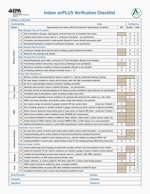
Indoor airPLUS Verification Checklist (PDF) (2 pp., 425 K)
Guidance for Completing the Indoor airPLUS Verification Checklist:
- Only ENERGY STAR certified homes verified to comply with these specifications can earn the Indoor airPLUS label. See Indoor airPLUS Construction Specifications for full descriptions of the requirements, terms, exceptions, abbreviations, references, and climate map used in this checklist. Verification is not complete until this checklist is completed in full and signed.
- Check one box per line. Check “N/A” for specifications that do not apply for specific conditions (e.g., climate) according to the Exceptions described in the Indoor airPLUS Construction Specifications. Check either “Builder” or “Rater” for all other items to indicate who verified each item. Items may be verified visually on site during construction, by reviewing photographs taken during construction, by checking documentation, or through equivalent methods as appropriate. If using a performance testing alternative to meet requirement
4.2 or 4.4, the box marked “Tested” must be checked and testing documentation must be pro-vided in the Home Energy Rating System (HERS) file.
- The Rater who conducted the verification, or a responsible party from the Rater’s company, must sign the completed verification checklist. The builder must sign the checklist if any items in the “Builder” column are checked, and by so doing accepts full responsibility for verifying that those items meet Indoor airPLUS requirements.
- The builder provides one copy of the completed and signed checklist for the buyer. The HERS or Rater files a copy with HERS and ENERGY STAR documentation (e.g., ENERGY STAR Certified Homes Version 3 Inspection Checklists) for the home.
- The checklist may be completed for a batch of homes using a RESNET-approved sampling protocol when
certifying homes as ENERGY STAR. For example, if the approved sampling protocol requires rating one in seven homes, then the checklist will be completed for the one home that was rated.
- Completed Verification Checklists should be mailed to iap@icfi.com
Note: The Indoor airPLUS Construction Specifications are designed to help improve indoor air quality (IAQ) in new homes compared with homes built to minimum code. These measures alone cannot prevent all IAQ problems; occupant behavior is also important. For example, smoking indoors would negatively impact a home’s IAQ and the performance of the specified Indoor airPLUS measures.
1. Moisture Control
Note: ENERGY STAR Thermal Enclosure System Rater Checklist requirements are an integral part of the Indoor airPLUS moisture control strategy. These requirements improve the control of air and thermal flows through building assemblies, which is critical to controlling water vapor migration and condensation. Since Thermal Enclosure System Rater Checklist compliance and verification are required for ENERGY STAR certification, these requirements are not re-stated in the Indoor airPLUS Construction Specifications. Download the checklists.
Water-Managed Site and Foundation
Please refer to the Technical Guidance: Moisture Control 1.1"
1.1 Provide site and foundation drainage as follows:
- Slope patio slabs, walks and driveways a minimum of 1/4 in. per ft. away from house, tamp back-fill to prevent settling, AND slope the final grade away from the foundation at a rate of 1/2 in. per ft. over a minimum distance of 10 ft. Where setbacks limit space to less than 10 ft., provide swales or drains designed to carry water away from the foundation. Back-fill tamping is not required if proper drainage can be achieved using non-settling compact soils, as determined by a certified hydrologist, soil scientist, or engineer.
- Install protected drain tile at the footings of basement and crawlspace walls, level or sloped to discharge to outside grade (daylight) or to a sump pump. The top of each drain tile pipe must always be below the bottom of the concrete slab or crawlspace floor. Each pipe shall be surrounded with at least 6 inches of 1/2 to 3/4 in. washed or clean gravel. The gravel layer shall be fully wrapped with fabric cloth to prevent fouling of the drain tile. If a drain tile discharges to daylight and radon-resistant features are required (see Specification 2.1), install a check valve at the drain tile outfall.
- Install a drain or sump in basement and crawlspace floors, discharging to daylight at least 10 ft. outside the foundation or into an approved sewer system. Floor drains are not required for slab-on-grade foundations.
1.2 Install capillary breaks as follows:
Please refer to the Technical Guidance: Moisture Control 1.2"
Beneath concrete slabs, including basement floors:
- Install a 4 in. layer of 1/2 in. diameter or greater clean aggregate, covered with 6 mil (or thicker) polyethylene sheeting, overlapped 6 to 12 in. at the seams, and in direct contact with the concrete slab above; OR
- Install a 4 in. uniform layer of sand, overlain with a layer or strips of geotextile drainage matting installed according to the manufacturer’s instructions, and covered with polyethylene sheeting overlapped 6 to 12 in. at the seams.
Crawlspace floors:
- Cover crawlspace floors with a concrete slab over 6 mil (or thicker) polyethylene sheeting overlapped 6 to 12 in. at the seams; OR
- Cover crawlspace floors with 6 mil polyethylene (10 mil recommended) sheeting, overlapped 6 to 12 in. and sealed or taped at the seams and penetrations. The sheeting shall be attached to walls and piers with adhesive and furring strips.
Exceptions:
- In areas of free-draining soils - identified as Group 1 by a certified hydrologist, soil scientist, or engineer through a site visit - a gravel layer or geotextile matting is not required under concrete slabs.
- Polyethylene sheeting is not required in Dry (B) climates, as defined by IECC Figure 301.1, unless the sheeting is required for radon resistance (see Specification 2.1).
1.3 Damp-proof or waterproof exterior surfaces of below-grade foundation walls as follows:
Please refer to the Technical Guidance: Moisture Control 1.3"
- Poured concrete, concrete masonry, and insulated concrete forms (ICFs) shall be finished with a damp-proof coating; AND
- Wood-framed walls shall be finished with trowel-on mastic and polyethylene, or with other waterproofing demonstrated to be equivalent.
Exceptions: Houses without below-grade walls.
1.4 Insulate and condition basements and crawlspaces as follows:
Please refer to the Technical Guidance: Moisture Control 1.4"
- Insulate crawlspace and basement perimeter walls according to IRC Table N1102.1 or IECC Table 402.1.1 (also see Specification 1.12); AND
- Seal crawlspace and basement perimeter walls to prevent outside air infiltration; AND
- Provide conditioned air at a rate not less than 1 cfm per 50 s.f. of horizontal floor area. If radon-resistant features are required (see Specification 2.1), do not install exhaust ventilation, as described in IRC section R408.3.2.1.
Exceptions:
- Homes built in areas designated as flood zones (conditioned crawlspaces are not recommended for use in flood zones).
- Raised pier foundation with no walls.
- Dry climates, as defined by IECC Figure 301.1.
- Marine climates, as defined by IECC Figure 301.1, if no air handler or return ducts are installed in the crawlspace.
Note: In each of the preceding exceptions, floors above unconditioned spaces shall be insulated to the IECC-specified R-value and sealed to prevent air infiltration.
Water-Managed Wall Assemblies
Please refer to the Technical Guidance: Moisture Control 1.5"
1.5 Install a continuous drainage plane behind exterior wall cladding, AND install flashing or an equivalent drainage system at the bottom of exterior walls to direct water away from the drainage plane and foundation. Drainage plane material shall overlap flashing and shall be fully sealed at all penetrations. Any of the following systems meet this requirement:
- Monolithic weather-resistant barriers (i.e., house wrap), shingled at horizontal joints and sealed or taped at all joints; OR
- Weather-resistant sheathings (e.g., faced rigid insulation), fully taped at all “butt” joints; OR
- Lapped shingle-style building paper or felt.
Note: Include weep holes for masonry veneer and weep screed for stucco cladding systems, according to the manufacturer’s specifications.
Please refer to the Technical Guidance: Moisture Control 1.6"
1.6 Fully flash all window and door openings, including pan flashing at sills, side flashing that extends over pan flashing, and top flashing that extends over side flashing.
Water-Managed Roof Assemblies
Please refer to the Technical Guidance: Moisture Control 1.7"
1.7 Direct roof water away from the house using gutters and downspouts that empty into lateral piping that deposits water on a sloping finish grade a minimum of 5 ft. from the foundation. Roofs designed without gutters are acceptable if they are designed to deposit rainwater to a grade-level rock bed with waterproof liner and drain pipe that deposits water on a sloping finish grade, as specified above. When lot space limits or prevents required grading, direct roof water to an underground catchments system (not connected to the foundation drain system) that deposits water a minimum of 10 ft. from the foundation. Rainwater-harvesting systems may be used to meet this requirement when they are designed to properly drain overflow, meeting discharge-distance requirements above.
Exception: Dry climates, as shown in IECC Figure 301.1.
Please refer to the Technical Guidance: Moisture Control 1.8"
1.8 Fully flash roof/wall intersections and all roof penetrations. Install step flashing at all roof/wall intersections, except metal and rubber membrane roofs, where continuous flashing should be installed. “Kick-out” flashing shall be installed at the low end of roof/wall intersections to direct water away from walls, windows, and doors below. In all cases, flashing shall extend at least 4 in. on the wall surface above the roof deck and shall be integrated with the drainage plane above (shingle style) to direct water onto and not behind flashing. In addition, intersecting wall siding should terminate a minimum of 1 in. above the roof, or higher according to the manufacturer’s recommendations.
Please refer to the Technical Guidance: Moisture Control 1.9"
1.9 Install self-sealing bituminous membrane or the equivalent at all valleys and roof decking penetrations for durability at potential failure points.
Exception: Dry climates, as shown in IECC Figure 301.1.
Please refer to the Technical Guidance: Moisture Control 1.10"
1.10 In colder climates (IECC Climate Zones 5 and higher), install self-sealing bituminous membrane or the equivalent ("ice flashing") over the sheathing at eaves to provide protection from ice dams. The ice flashing shall extend up the roof plane from the eave to a point at least 2 ft. inside the vertical plane of the exterior wall.
Exception: Climate Zones 1 to 4, as shown in IECC Figure 301.1.
Interior Water Management
Please refer to the Technical Guidance: Moisture Control 1.11"
1.11 Install moisture-resistant materials and moisture-protective systems in vulnerable areas. For example:
- Install water-resistant hard-surface flooring in kitchens, bathrooms, entryways, laundry areas, and utility rooms. Do not install wall-to-wall carpet adjacent to toilets and bathing fixtures (i.e., tubs and showers).
- Install moisture-resistant backing material (i.e., cement board or the equivalent, but not paper-faced wall board) behind tub and shower enclosures.
- Install all condensate discharge according to IRC section M1411.3.
- Insulate piping installed in exterior walls.
Please refer to the Technical Guidance: Moisture Control 1.12"
1.12 Do not install continuous vapor barriers on the interior side of exterior walls that have high condensation potential (e.g., below-grade exterior walls in most climates and above-grade exterior walls in warm-humid climates). For the purpose of this specification, vapor barriers are materials that have a perm rating of 0.1 or less (see manufacturer's product specifications or 2005 ASHRAE Handbook of Fundamentals, Chapter 25, Tables 7A and 7B).
Please refer to the Technical Guidance: Moisture Control 1.13"
1.13 Do not install building materials that have visible signs of water damage or mold. In addition, interior walls shall not be enclosed (e.g., with drywall) if either the framing members or insulation has a high moisture content. For wet-applied insulation, follow the manufacturer’s drying recommendations.
Advisory: Lumber should not exceed 18 percent moisture content.
2. Radon Control
2.1 Homes built in EPA Radon Zone 1 (see EPA's Map of Radon Zones) shall be constructed with approved radon-resistant features according to EPA's "Building Radon Out"; NFPA 5000, Chapter 49; IRC, Appendix F; CABO, Appendix F; or ASTM E1465. The following requirements shall be verified:
- Capillary break installed according to Specification 1.2; AND
- A 3 or 4 in. diameter gas-tight vertical vent pipe, clearly labeled “Radon Pipe” or “Radon System,” connected to an open T-fitting in the aggregate layer (or connected to geotextile drainage matting according to the manufacturer’s instructions) beneath the polyethylene sheeting, extending up through the conditioned spaces and terminating a minimum of 12 in. above the roof opening. For crawlspaces, install at least 5 ft. of horizontal perforated drain tile on either side of the T-fitting, attached to the vertical radon vent pipe beneath the sheeting and running parallel to the long dimension of the house; AND
- Radon fan installed in the attic (i.e., an active system) OR an electrical receptacle installed in an accessible attic location near the radon vent pipe (i.e., a passive system) to facilitate future fan installation if needed; AND
- Foundation air sealing with polyurethane caulk or the equivalent at all slab openings, penetrations, and control or expansion joints. Sump covers also shall be air sealed (e.g., mechanically attached with full gasket seal or equivalent.)
Exception: The Indoor airPLUS Construction Specifications recommend, but do not require, radon-resistant features for homes built in EPA Radon Zones 2 and 3 unless required by local building codes (see Advisory 1).
Advisories:
- Elevated levels of radon have been found in homes built in all three zones on EPA’s Map of Radon Zones. Consult your state’s radon coordinator for current information about radon in your area. Go to EPA's Radon Where You Live page and click on your state for contact information.
- If soil or groundwater contamination is suspected on or near the building site (e.g., former industrial sites), volatile contaminants or breakdown products may pose an IAQ risk through soil gas intrusion. In such cases, EPA recommends radon-resistant features consistent with Specification 2.1, which can prevent the intrusion of soil vapor into a house. See the EPA Vapor Intrusion Primer or ASTM E2600 for more information, or consult your state or tribal Brownfield voluntary cleanup program or environmental regulatory agency for information on the risks of vapor intrusion in your area.
2.2 Provide two radon test kits designed for 48-hour exposures for the buyers of homes in EPA Radon Zones 1 and 2, including test kit instructions and EPA guidance on follow-up actions to be taken in response to the test results.
Advisory: The U.S. Surgeon General and EPA recommend that all homes (including homes built in Radon Zone 3) be tested for radon. Refer interested buyers to www.epa.gov/radon for more information.
3. Pest Barriers
3.1 Minimize pathways for pest entry by sealing penetrations and joints in and between the foundation and exterior wall assemblies with blocking materials, foam, and polyurethane caulk or the equivalent. Sump pit covers shall be air sealed (e.g., mechanically attached with full gasket seal or the equivalent).
Advisories:
- Additional precautions should be taken in areas of “Heavy” termite infestation probability (as identified by IRC Figure 301.2[6]) as follows:
- Foundation walls should be solid concrete or masonry with a top course of solid block, bond beam, or concrete-filled block; AND
- Interior concrete slabs should be constructed with 6 x 6 in. welded wire fabric or the equivalent, and concrete walls should be constructed with reinforcing rods to reduce cracking; AND
- Sill plates should be made of preservative-treated wood.
- The following additional precautions should be taken in areas of “Very Heavy” termite infestation probability (as identified by IRC Figure 301.2[6]) i.e., Alabama, Florida, Georgia, Louisiana, Mississippi, South Carolina, and parts of California and Texas:
Below-grade:
- Foam plastic insulation should not be installed on the exterior face of below-grade foundation walls or under slabs.
- Foam plastic insulation installed on the exterior of above-grade foundation walls should be kept a minimum of 6 in. above the final grade and any landscape bedding materials, and should be covered with moisture-resistant, pest-proof material (e.g., fiber cement board or galvanized insect screen at the bottom-edge of openings).
- Foam plastic insulation applied to the interior side of conditioned crawlspace walls should be kept a minimum of 3 in. below the sill plate.
- Foam plastic insulation should not be installed on the exterior face of below-grade foundation walls or under slabs.
3.2 Provide corrosion-proof rodent/bird screens (e.g., copper or stainless steel mesh) for all building openings that cannot be fully sealed and caulked (e.g., ventilation system intake/exhaust outlets and attic vent openings). This requirement does not apply to clothes dryer vents.
4. HVAC Systems
Heating and Cooling Equipment
4.1 Heating and cooling design loads shall be determined for each room according to ACCA Man J, ASHRAE Handbooks, or equivalent software. Heating and cooling equipment shall be properly sized and selected to meet the design loads and accommodation must be made for pressure drop from specified filter (see Specification 4.7). This requirement shall be met by an ENERGY STAR HVAC QI Certificate (where available) OR verification of all the following:
- Documentation of design load calculations (i.e., load calculation worksheet or software report), AND
- System design documentation (i.e., sizing calculations and equipment performance information), AND
- Verification that outdoor and indoor coils match in accordance with the AHRI Directory of Certified Product Performance. For more information, see www.ahridirectory.org

4.2 Duct system(s) shall be designed according to ACCA Man D, ASHRAE Handbooks, or equivalent software AND installed to be substantially airtight, properly balanced, and protected from construction debris. This requirement shall be met by an ENERGY STAR HVAC QI Certificate (where available) OR verification of all the following prescriptive requirements, OR the Performance Test Alternative below:
- Design verified by appropriate documentation (i.e., duct-sizing worksheet or annotated layout), AND
- Duct system verified to meet the following additional requirements:
- Seams in the HVAC cabinet, plenum, and adjacent ductwork shall be sealed with mastic systems, tape that meets the applicable requirements of UL 181A or UL 181B, or gasket systems.
- Building cavities shall not be used as part of the forced air supply or return systems.
- Duct openings shall either be covered during construction or vacuumed out thoroughly prior to installing registers, grilles, and diffusers (see Specification 7.1)
Performance Test Alternative:
- Room-by-room airflows balanced and verified within +/-20% of calculated room airflows to meet design loads (see Specification 4.1), except for baths, closets, and pantries, AND
- Duct system TOTAL leakage test no greater than 6 cfm per 100 s.f. of floor area (or 9% design fan flow), measured at 25 Pa, with duct boots and air handler in place, according to ASTM E1554, ASHRAE 152, or other RESNET-approved method.
4.3 No air-handling equipment or ductwork shall be located in garages.
Note: Ducts and equipment may be located in framing spaces or building cavities adjacent to garage walls or ceilings if they are separated from the garage space with a continuous air barrier (see ENERGY STAR Thermal Enclosure System Rater Checklist Guide).
4.4 Room pressure differentials shall be minimized by installing transfer grilles or jump ducts for any closed room that does not have a dedicated return, except for baths, kitchens, closets, pantries, and laundry rooms. The opening size shall be 1 square in. capacity (grille area) per cfm of supply (including free area undercut below door as part of the area).
Performance Test Alternative: Measured pressure differential no greater than 3 Pa (0.012 in. w.c.) between closed rooms and adjacent spaces that have a return.
Ventilation
4.5 Provide mechanical whole-house ventilation meeting all ASHRAE 62.2 requirements. The following requirements shall be visually verified:
- Whole house mechanical ventilation system & controls shall be installed to deliver the prescribed outdoor air ventilation rate (ASHRAE 62.2 section 4), including ventilation restrictions in ASHRAE 62.2 section 4.5 (e.g., not greater than 7.5 cfm/100 s.f. in “Warm-Humid” climates as defined by IECC Figure 301.1); AND
- Transfer air (i.e., air from adjacent dwelling units or other spaces such as garages, crawlspaces, or attics) shall not be used to meet ventilation requirements (ASHRAE 62.2 section 6.1); AND
- Outdoor air inlets shall be located a minimum of 10 ft. from contaminant sources (ASHRAE 62.2 section 6.8); AND
- Airflow shall be tested to meet rated fan airflow (at 0.25 in. w.c.) OR verify duct(s) sized according to the requirements of ASHRAE 62.2 Table 7.1 and the manufacturer’s design criteria (ASHRAE 62.2 section 7.3).
Note: Outdoor air ducts connected to the return side of an air handler shall be permitted as supply ventilation only if the manufacturers’ requirements for return air temperature are met (e.g., most manufacturers recommend a minimum of 60 degrees F air flow across furnace heat exchangers).
4.6 Provide local exhaust ventilation to the outdoors for known pollutant sources, as follows:
- Provide local mechanical exhaust ventilation to the outdoors in each bathroom and kitchen, meeting ASHRAE 62.2 section 5 requirements. In addition, all bathroom ventilation fans shall be ENERGY STAR qualified unless multiple bathrooms are exhausted with a multi-port fan.
- Conventional clothes dryers shall be vented to the outdoors. Electric condensing dryers are not vented and shall be plumbed to a drain according to the manufacturer’s instructions.
- If a central vacuum system is installed, the system shall be vented outdoors at least 10 ft. from the ventilation system air inlets (see Specification 4.5), or the power/filtration unit shall be installed in the garage according to the manufacturer’s instructions.
Air Cleaning and Filtration
4.7 Central forced-air HVAC systems shall include a filtration system meeting the following requirements:
- HVAC filters shall be rated MERV 8 or higher according to ASHRAE 52.2 (at approximately 295 fpm).
- There shall be no visible bypass between the filter and the filter rack.
The filter access panel shall include gasket material or comparable sealing mechanism to prevent air leakage, and it shall fit snugly against the exposed edge of the installed filter when closed to prevent bypass.
- No air-cleaning equipment designed to produce ozone (i.e., ozone generators) shall be installed.
Advisory: Filters perform best when the filter rack design includes the following features, which are also included in some manufacturers’ filter media boxes:
- Flexible, air-tight (e.g., closed-cell foam) gasket material on the surface that contacts the air-leaving (downstream) side of the filter, AND
- Friction fit or spring clips installed on the upstream side of the filter to hold it firmly in place.
Dehumidification
4.8 In "Warm-Humid" climates as defined by IECC Figure 301.1 (i.e., Climate Zone 1 and portions of Zones 2 and 3A below the white line), equipment shall be installed with sufficient latent capacity to maintain indoor relative humidity (RH) at or below 60 percent. This requirement shall be met by either:
- Additional dehumidification system(s), OR
- A central HVAC system equipped with additional controls to operate in dehumidification mode.
Exception: Climate Zones 4-8, 3B, 3C, and the portions of 3A and 2B above the white line as shown by IECC Figure 301.1.
Advisory: Although not required to meet this specification, independent dehumidification is recommended in Climate Zones 4A and 3A above the white line as shown in IECC Figure 301.1.
5. Combustion Pollutant Control
Combustion Source Controls
5.1 For combustion space-heating and water-heating equipment located in conditioned spaces:
- Gas-fired furnaces/boilers shall be direct vented, except in Climate Zones 1-3 as shown in IECC Figure 301.1.
- Oil-fired furnaces/boilers shall be power vented or direct vented, except in Climate Zones 1-3 as shown in IECC Figure 301.1.
- Combustion water heaters shall be power vented or direct vented.
- No unvented combustion space-heating appliances shall be permitted.
Exception: Houses with no combustion heating equipment located in conditioned spaces.
Note: Unfinished basements and crawlspaces (except raised pier foundations with no walls) and attached garages that are air-sealed to the outside and intended for use as work space or living space, are considered “conditioned spaces” for the purpose of this requirement.
5.2 Fireplaces and other fuel-burning space-heating appliances located in conditioned spaces shall be vented to the outdoors and supplied with adequate combustion and ventilation air according to the manufacturers' installation instructions, AND they shall meet the following energy efficiency and emissions standards and restrictions:
- Masonry fireplaces are not permitted, with the exception of "masonry heaters" as defined by ASTM E1602 and section 2112.1 of the International Building Code (i.e., fireplaces engineered to store and release substantial portions of heat generated from a rapid burn).
- Factory-built, wood-burning fireplaces shall meet the certification requirements of UL 127 and emission limits found in the EPA Standard for New Residential Wood Heaters.
- Wood stove and fireplace inserts as defined in section 3.8 of UL 1482 shall meet the certification requirements of that standard, and they shall meet the emission requirements of the EPA Standards for New Residential Wood Heaters and WAC 173-433-100 (3).
- Pellet stoves shall meet the requirements of ASTM E1509.
Decorative gas logs as defined in K.1.11 of NFPA 54 (National Fuel Gas Code) are not permitted. - Unvented combustion space-heating appliances are not permitted.
Advisory: To minimize the potential for spillage or back-drafting, fireplaces and fuel-burning appliances located in conditioned spaces should be installed in compliance with ASHRAE 62.2 (section 6.4) or by conducting a Worst Case Depressurization Combustion Air Zone (CAZ) Test according to an established protocol.
5.3 All homes equipped with combustion appliance(s) or an attached garage shall have a carbon monoxide (CO) alarm installed in a central location in the immediate vicinity of each separate sleeping zone (e.g., in a hallway adjacent to bedrooms.) The alarm(s) shall be hard-wired with a battery back-up function and placed according to NFPA 720. The alarms shall be certified by either CSA 6.19-01 or UL 2034.
5.4 Reduce exposure to environmental tobacco smoke (ETS) in multi-family buildings by:
- Prohibiting smoking in indoor common areas, specified explicitly in building rental/lease agreements or condo/co-op association covenants and restrictions, AND
- Locating designated outdoor smoking areas a minimum of 25 ft. from entries, outdoor air intakes, and operable windows, AND
- Minimizing uncontrolled pathways for ETS transfer between individual dwelling units by sealing penetrations in the walls, ceilings, and floors of dwelling units, sealing vertical chases adjacent to dwelling units, and applying weather stripping to all doors in dwelling units leading to common hallways.
Attached Garage Isolation
5.5 Attached garages shall be isolated from conditioned spaces as follows:
- Common walls and ceilings between attached garages and living spaces shall be visually inspected to ensure they are air-sealed before insulation is installed.
- All connecting doors between living spaces and attached garages shall include an automatic closer, and they shall be installed with gasket material or be made substantially air-tight with weather stripping.
5.6 Attached garages shall include an exhaust fan, with a minimum installed capacity of 70 cfm, rated for continuous operation, and installed to vent directly outdoors. If automatic fan controls are installed, they shall activate the fan whenever the garage is occupied and for at least 1 hour after the garage has been vacated.
Advisory: ENERGY STAR qualified fans are highly recommended.
6. Low-Emission Materials
Note: The evaluation, certification, and labeling of products for indoor VOC emissions is complex and evolving. EPA has not established threshold levels for indoor VOC emissions from any of the product categories addressed in these specifications. The third-party programs referenced in these specifications include U.S. programs that are designed to reduce indoor human exposure to individual VOCs of potential concern for human health effects, compared to similar products not certified as low-VOC or no-VOC. EPA will consider modifying these specifications to include additional third-party programs as appropriate.
6.1 Structural plywood, oriented strand board (OSB), and composite wood products (i.e., hardwood plywood, particleboard, medium density fiberboard [MDF], and cabinetry made with these products) shall be third-party certified for compliance with industry and federal standards, as follows:
- Structural plywood and OSB shall be certified compliant with PS1 or PS2, as appropriate, and shall be made with moisture-resistant adhesives as indicated by “Exposure 1” or “Exterior” on the American Plywood Association (APA) trademark.
- Hardwood plywood shall be certified compliant with the formaldehyde emissions requirements of ANSI/HPVA HP-1-2004 and U.S. HUD Title 24, Part 3280, OR certified compliant with CA Title 17.
- Particleboard and MDF shall be certified compliant with the formaldehyde emissions requirements of ANSI A208.1 and A208.2, respectively, and U.S. HUD Title 24, Part 3280, OR certified compliant with EPPS CPA 3-08 by the CPA Grademark certification program, OR certified compliant with CA Title 17.
- Cabinetry shall be made with component materials that are certified to comply with all the appropriate standards above OR shall be registered brands or produced in registered plants certified under KCMA’s Environmental Stewardship Certification Program (ESP 01-06).
Note: In California, composite wood products shall be certified compliant with CA Title 17 as appropriate.
6.2 Interior paints and finishes, including 90% or more of such products applied to interior surfaces of homes, shall be certified low-VOC or no-VOC by one of the following:
- Green Seal Standard GS-11, OR
- Greenguard Certification for Paints and Coatings, OR
- Scientific Certification Systems (SCS) Standard EC-10.2-2007, Indoor Advantage Gold, OR
- Master Painters Institute (MPI) Green Performance Standards GPS-1 or GPS-2, OR
- A third-party low-emitting product list based on CA Section 01350 , e.g., the CHPS List
6.3 Carpets and carpet adhesives shall be labeled with, or otherwise documented as meeting, the Carpet & Rug Institute (CRI) Green Label Plus or Green Label testing program criteria. Carpet cushion (i.e., padding) shall similarly be certified to meet the CRI Green Label testing program criteria.
7. Home Commissioning
7.1 HVAC systems and ductwork shall be verified to be dry and clean and installed according to their design as documented by an ENERGY STAR HVAC QI Certificate (where available) OR as follows:
- Inspect ductwork before installing registers, grilles, and diffusers to verify it is dry and substantially free of dust or debris, and that there are no disconnects or visible air gaps between boots and framed openings. If duct openings were not covered during construction, thoroughly vacuum out each opening prior to installing registers, grilles, and diffusers.
- Inspect air-handling equipment and verify that heat exchangers/coils are free of dust caused by construction activities (e.g., drywall, floor sanding) AND the filter is new, clean and meets specified MERV rating (see Specification 4.7). After installation of registers, grilles, and diffusers, verify detectable airflow from each supply outlet.
- Verify the HVAC contractor has documented measured airflow or pressure drop across the cooling coil or heat exchanger within +/- 15% of system design airflow, or the manufacturer-specified operating range, tested according to ASTM E1554, ASHRAE 152, or an equivalent method.
- Verify the HVAC contractor has documented the installation and testing of proper refrigerant charge. This requirement may be met by any of the following methods according to ACCA 5 QI-2007:
- Superheat method test measurement within 5% of the manufacturer-recommended charge, OR
- Subcooling method test measurement within 3% of the manufacturer-recommended charge, OR
- Other equivalent method/tolerance approved by the equipment manufacturer.
Note: If weather conditions do not meet required test conditions, verify that the builder or contractor has arranged for future testing.
7.2 Verify that the home has been ventilated with outside air at the highest rate practical during and shortly after installing products that are known sources of contaminants (e.g., cabinets, carpet padding, and painting) and during the period between finishing and occupancy, meeting ventilation requirements for outdoor air flow and humidity control (see Specifications 4.5 and 4.8). If whole house ventilation cannot be scheduled prior to occupancy, advise the buyer to operate the ventilation system at the highest rate it can provide during the first few months of occupancy, meeting the above requirements.
7.3 Provide for buyers a completed checklist and other required documentation about the IAQ features of their home, including:
- A copy of the Indoor airPLUS verification checklist or other written documentation indicating compliance with all required measures from the Indoor airPLUS construction specifications, signed by an official representative of the builder, AND
- HVAC, duct, and ventilation system design documentation (i.e., airflow requirements) or performance test results (i.e., measured cfm) required by Specifications 4.1, 4.2, and 4.5, respectively, and a description of the ventilation system (i.e., system type, components, and controls), AND
- Operations and maintenance instruction manuals for all installed equipment and systems addressed by Indoor airPLUS requirements, including HVAC systems and accessories, combustion appliances, and radon system literature and test kit instructions.
Abbreviations
Additional Resources
Other glossaries exist within various Indoor Air topics that fall under Indoor Air Quality [see Indoor Air Quality, Radon, Mold]
See also:
- IAQ Tools for Schools Kit, IAQ Reference Guide - Appendix M - Glossary and Acronyms
- Indoor Air Quality Building Evaluation and Assessment Model (I-BEAM): Glossary of IAQ Terms
- Building Air Quality: A Guide for Building Owners and Facility Managers - Appendix F: Glossary and Acronyms (PDF) (4 pp, 14KB, About PDF)
- cfm
- cubic feet per minute (1 (cubic foot) per minute = 0.000471947443 m3 / s)
- fpm
- feet per minute
- ft.
- feet
- HERS
- Home Energy Rating System
- HVAC
- heating, ventilating, and air-conditioning
- IAQ
- indoor air quality. IAQ is a term referring to the air quality within and around buildings and structures, especially as it relates to the health and comfort of building occupants.
- in.
- inches
- mil
- common term to describe plastic sheeting thickness; 1 mil equals 0.001 inches
- min.
- minimum
- MERV
- Minimum Efficiency Reporting Value; defined in ASHRAE 52.2
- Pa
- Pascals. the derived SI unit of pressure; the pressure exerted on an area of 1 square metre by a force of 1 newton; equivalent to 10 dynes per square centimetre or 1.45 x 10 -4 pound per square inch .
- QI
- Quality Installation (ENERGY STAR HVAC QI)
- s.f.
- square feet
- spec
- specification
- VOC
- Volatile Organic Compound
- w.c.
- water column
References
- ACCA Man D: ACCA Manual D: Residential Duct Systems. 1995. Air Conditioning Contractors of America.
- ACCA Man J: ACCA Manual J: Residential Load Calculation. 2006. Air Conditioning Contractors of America.
- ACCA 5 QI-2007: ANSI/ACCA Standard 5 QI-2007: HVAC Quality Installation Specification. 2007. Air Conditioning Contractors of America.
- AHRI Directory: AHRI Directory of Certified Product Performance. Air-Conditioning, Heating, and Refrigeration Institute.
- ANSI A208.1: ANSI A208.1: Standard for Wood Particleboard. 1999. American National Standards Institute.
- ANSI A208.2: ANSI A208.2: Standard for Medium Density Fiberboard (MDF). 2002. American National Standards Institute.
- ANSI/HPVA HP-1-2004: American National Standard for Hardwood and Decorative Plywood. 2004. American National Standards Institute / Hardwood Plywood and Veneer Association.
- ANSI Z21.88/CSA 2.33: ANSI Standard Z21.88-2005/CSA Standard 2.33-2005: Vented Gas Fireplace Heaters. 2005. American National Standards Institute / Canadian Standards Association.
- ASHRAE Handbooks: ASHRAE Handbook Series. American Society of Heating, Refrigeration, and Air-Conditioning Engineers.
- ASHRAE 52.2: ANSI/ASHRAE Standard 52.2-2007: Method of Testing General Ventilation Air-Cleaning Devices for Removal Efficiency by Particle Size. 2007. American Society of Heating, Refrigeration, and Air-Conditioning Engineers.
- ASHRAE 62.2: ANSI/ASHRAE Standard 62.2-2007: Ventilation and Acceptable Indoor Air Quality in Low-Rise Residential Buildings. 2007. American Society of Heating, Refrigeration, and Air-Conditioning Engineers.
- ASHRAE 152: ANSI/ASHRAE Standard 152-2004: Method of Test for Determining the Design and Seasonal Efficiencies of Residential Thermal Distribution Systems. 2004. American Society of Heating, Refrigeration, and Air-Conditioning Engineers.
- ASTM E1465: ASTM Standard E1465-06: Standard Practice for Radon Control Options for the Design and Construction of New Low-Rise Residential Buildings. 2006. American Society for Testing and Materials.
- ASTM E1509: ASTM Standard E1509-04: Standard Specification for Room Heaters, Pellet Fuel-Burning Type. 2004. American Society for Testing and Materials. ASTM E2600: ASTM Standard E2600-08: Standard Practice for Assessment of Vapor Intrusion into Structures on Property Involved in Real Estate Transactions. 2008. American Society for Testing and Materials.
- ASTM E1554: ASTM Standard E1554-03: Standard Test Methods for Determining External Air Leakage of Air Distribution Systems by Fan Pressurization. 2003. American Society for Testing and Materials.
- ASTM E1602: ASTM Standard E1602-03: Standard Guide for Construction of Solid Fuel Burning Masonry Heaters. 2003. American Society for Testing and Materials.
- CABO: CABO One and Two Family Dwelling Code. 1998. Council of American Building Officials.
- CA Section 01350:
California Section 01350 : Special Environmental Requirements Specification, including Addendum 2004-1: Standard Practice for the Testing of Volatile Organic Emissions from Various Sources Using Small-Scale Environmental Chambers. 2004. State of California.
- CA Title 17: California Code of Regulations, Title 17, sections 93120 - 93120.12. 2008. State of California.
- CHPS List: Collaborative for High Performance Schools (CHPS) Low Emitting Materials List.
- CRI Green Label: Carpet and Rug Institute Green Label Testing Programs.
- CSA 6.19-01: CAN/CSA Standard 6.19-01: Residential Carbon Monoxide Alarming Devices. 2001. Canadian Standards Association.
- ENERGY STAR HVAC QI: ENERGY STAR HVAC Quality Installation (pilot program). U.S. Environmental Protection Agency.
- ENERGY STAR Thermal Enclosure System Rater Checklist: U.S. Environmental Protection Agency.
- EPA Building Radon Out: Building Radon Out: A Step-by-Step Guide On How to Build Radon-Resistant Homes. 2001. U.S. Environmental Protection Agency.
- EPA Radon Maps: EPA’s Map of Radon Zones. 2008. U.S. Environmental Protection Agency.
- EPA Standard for New Residential Wood Heaters: 40 CFR Part 60, subpart AAA: Standards of Performance for New Residential Wood Heaters. 1988. U.S. Environmental Protection Agency.
- EPA Vapor Intrusion Primer: Brownfields Technology Primer: Vapor Intrusion Considerations for Redevelopment. 2008. U.S. Environmental Protection Agency.
- EPPS CPA 3-08: Environmental Preferable Product Specification CPA 3-08. 2008. Composite Panel Association.
- Greenguard Certification for Paints and Coatings: Greenguard Certification Program for Low Emitting Products: Paints and Coatings. 2005. Greenguard Environmental Institute.
- Green Seal Standard GS-11: GS-11: Green Seal Environmental Standard for Paints and Coatings. 2008. Green Seal, Inc.
- HUD Title 24: U.S. HUD Title 24 Part 3280: Manufactured Home Construction and Safety Standards. 1993. U.S. Department of Housing and Urban Development.
- IBC: International Building Code. 2003. International Code Council, Inc.
- IECC: International Energy Conservation Code. 2006. International Code Council, Inc.
- IRC: International Residential Code for One- and Two-Family Dwellings. 2006. International Code Council, Inc.
- KCMA ESP 01-06: Environmental Stewardship Certification Program. 2006. Kitchen Cabinet Manufacturer’s Association.
- MPI GPS-1 and GPS-2: Master Painters Institute (MPI) Green Performance Standards for Paints and Coatings [GPS-1 and GPS-2]. 2008. Master Painters Institute, Inc.
- NFPA 54: National Fuel Gas Code. 2006. National Fire Protection Association.
- NFPA 720: Standard for the Installation of Household Carbon Monoxide (CO) Warning Equipment. 2005. National Fire Protection Association.
- NFPA 5000: Building and Construction Safety Code. 2006. National Fire Protection Association.
- PS1-07: Voluntary Product Standard for Structural Plywood. 2007. American Plywood Association.
- PS2-04: Voluntary Product Standard for Wood-based Structural-use Panels. 2004. American Plywood Association.
- RESNET: Mortgage Industry National Home Energy Rating System Standards. 2006. Residential Energy Services Network.
- SCS-EC-10.2-2007: Scientific Certification Systems (SCS) Indoor Air Quality Performance Environmental Certification Program: Indoor Advantage Gold. 2007. Scientific Certification Systems.
- UL 127: Standard for Factory-Built Fireplaces. 1996. Underwriters Laboratories, Inc.
- UL 181A: Standard for Closure Systems for Use With Rigid Air Ducts. 2005. Underwriters Laboratories, Inc.
- UL 181B: Standard for Closure Systems for Use With Flexible Air Ducts and Air Connectors. 2005. Underwriters Laboratories, Inc.
- UL 1482: Standard for Solid-Fuel Type Room Heaters. 1996. Underwriters Laboratories, Inc.
- UL 2034: Standard for Single and Multiple Station Carbon Monoxide Alarms. 1996. Underwriters Laboratories, Inc.
- WAC 173-433-100 (3): Washington State Code, Chapter 173-433: Solid Fuel Burning Devices, section 100 (3) Emissions performance standards. 1993.
Climate Zones Throughout the Continental United States

Download and print a version of the map (PDF, 1 page, 296 K)
Figure 301.1, 2006 International Energy Conservation Code®
Copyright 2006, Washington, DC: International Code Council. Reproduced by permission. All rights reserved.