
Field Performance Testing
March, 2002 – January, 2003
USDA Forest Service and U.S. Access Board
prepared by:
Theodore Laufenberg and Jerrold Winandy
Performance Engineered Composites
USDA-Forest Service, Forest Products Laboratory
One Gifford Pinchot Drive, Madison, WI 53726The project was conducted cooperatively with the United States Architectural and Transportation Accessibility Compliance Board (U.S. Access Board).
Related Documents: Phase III Reports
Play Surfaces: Installation and Serviceability Results
(December 2004)
Accessible Trails: Installation and Serviceability Results
(November 2004)
In our previous work (Phase I Final Report: Interagency Agreement 00-CO-11111124-154, 2002 by Laufenberg et al 2001), basic processing techniques to produce wood-resin composite playground surfaces with improved accessibility for users of wheelchairs and walkers were developed. There was also a need to retain adequate impact-energy absorption performance attributes to preclude some head and limb injuries to playground users. The composite systems developed consisted of a combination of a resin and engineered wood fiber (EWF) in the top surface layer with just EWF below. That work identified designs using compatible resin (e.g. latex, silicone and polyurethane) binders and various species and textures of engineered wood fiber (EWF). It included laboratory testing of energy absorption and surface firmness on trial surfaces in plywood boxes 0.5 m x 0.5 m (18” x 18”) at a uniform depth of 0.3 m (12”). Seven systems were identified as having reasonable performance and thence recommended for Phase II outdoor field evaluations.
Phase II research focused on outdoor evaluation of the binder/fiber options identified as minimally acceptable and promising in our Phase I evaluations. The Phase II work studied field durability and looked at changes in performance by quantifying the impact and accessibility of these novel surfaces after field exposure. This series included seven surface treatments, and a control surface, installed in a series of outdoor test beds in Madison WI to gather field experience on long-term performance and durability. The binders evaluated were a) synthetic latex emulsion, b) a low molecular weight silicone and c) foaming and non-foaming resilient polyurethanes. Systems were evaluated over a 6-month period.
Stabilizing binders needed to be applied on-site or mixed with the EWF no longer than an hour prior to placement on the ground surface. Practical considerations evaluated were a) cure/set time prior to surface use, b)range of EWF moisture and temperature conditions acceptable for use, and c) emissions of fumes or odors, workable exotherms, and toxic or other chemical release/concerns from the binder/EWF mixture needed to be minimal.
The development guidelines require that the system provide impact safety and good accessibility. The Americans with Disabilities Act (ADA, 1990) states that accessible surfaces shall be stable, firm, and slip-resistant. These three criteria have not been defined adequately for measurement on any specific surface. Therefore, we’re required to make this evaluation subjectively. In addition, each Resin-EWF system should allow water to drain from both the bonded surface and unbonded interior of the mat system. This is critical in reducing the biodeterioration potential of the wood fiber and in maintaining cushioning behavior of EWF during sub-freezing temperatures.
Impact safety is quantifiable via the ASTM F1292 and F355. Preliminary tests using a portable impact test provided an indication of stabilizing binder cushioning performance and a small-scale test meant to simulate a wheelchair (ASTM F1951 rotational penetrometer test) was used to assess accessibility potential. Two cooperators (Zeager Bros. Inc. and Beneficial Designs Inc.) provided these portable test apparatuses and training in their use.
The desired resin/EWF system needs to provide impact safety and appropriate accessibility over a number of seasons. It must retain the performance characteristics of impact-energy absorption and surface resiliency. We need to evaluate the ability of the mat to drain water from its bonded surface and unbonded interior to reduce biodeterioration and maintain cushioning behavior during freezing temperatures. Impact and accessibility of these novel surfaces were measured after a six (6) month field exposure from April-October 2002 in Madison WI. Subsequent 12-month exposure performance testing of each Phase II EWF surface will be evaluated in the Spring of 2003 and reported in a later report.
Bonded Impact/cushioning Surfaces
Eight different surface test specimens were formed with surface dimensions of 1.2m x 1.2m with a depth of 0.3m (48”x48”x 12”) in Madison WI (Figure 1). Seven had a top layer of bonded resin/EWF and the eighth was a full-depth EWF control. Two additional surfaces were made (Figure 1, A1 and E1) and each were duplicates of other surfacing test areas. A1 and E1 were on a slope to assure drainage of the entire test surface. All surfaces used Engineered Wood Fiber (EWF), as defined by ASTM F2075-01. All surfaced specimens were compacted to simulate the finished surface of a play area. Given that there is no industry, governmental, or association definition or standard for compacting EWF, we followed playground industry installation practices.

Figure 1. Overview of the test surfaces in Madison, Wisconsin. From top left along the concrete edge the test surfaces are A1, A2, B, C, D; then from top right toward the bottom, E1, F, G, E2, H (Note: A1 and E1 were not useable due to slope in excess of 5%).
| Surface ID | Matrix Adhesive | Top Surface Thickness |
|---|---|---|
| A2 | 35% Silicone | 50 mm (2") |
| B | 40% Silicone | 38 mm (1 ½") |
| C | 30% Polyurethane | 38 mm (1 ½") |
| D | 30% Polyurethane | 25 mm (1") over geotextile |
| E2 | None | None |
| F | 30% Latex | 63 mm (2 ½”) |
| G | 25% Latex | 50 mm (2”) over geotextile |
| H | 30% Vitriturf | 38 mm (1 ½”) |
All Phase II surfaces (Table 1) were selected based on an evaluation of Phase I results. Any Phase I system which was shown to have either undesirable surface stability or resiliency was eliminated from Phase II testing. All Phase II surfaces were fabricated from EWF matched to Phase I materials and obtained from a commercial supplier (Zeager Bros. Obtained from their Oskaloosa, Iowa licensee.). A baseline “control” test surface was also made with only EWF.
Four bonding systems were used to fabricate these surfaces.These systems* are:
a) silicone-based, Dow-Corning AllGuard, a waterproofing coating,
b) a synthetic latex, Midwest Industrial Soil-Sement
c) a foaming polyurethane (Franklin ReacTITE 8143), and
d) a non-foaming polyurethane (Vitricon’s) Vitriturf
* Tradenames used only for the reader’s information and do not constitute an endorsement by USDA Forest Service.
One interfacial treatment was used for two of the surfaced specimens. A 1.2 m x 1.2 m (48 in. x 48 in.) single ply layer of lightweight polyolefin landscaping geotextile was placed between the unbonded and bonded layers of these specimens. The geotextile was intended to provide cotinuity for the thinner bonded surface layers in the event that they might fracture through the entire thickness. When this happens the layer could be ejected from its original position and become a hazard on the remaining bonded surface.
In accordance with standard EWF design and construction practice (Figure 2), the full depth surfaces were prepared to the same requirements needed for permanent playground surfaces. Our installation began on February 27, 2002 and was completed with bonded top surfaces within six weeks. The installation steps were:
1)Excavate area 380 mm (15 in.) in depth with a minimum of 1% grade to ensure proper drainage. All roots, stones, and vegetation were removed.
2)Place a diversion along the slope above the test area to assure no direct site drainage into the surfaced area.
3)Cover entire subgrade with one layer of geotextile. Overlap courses of geotextile by 125 mm (5 in.).
4)Cover the excavated surface to a 75 mm (3 in.) depth of washed 18 mm (¾-inch) stone.
5)Cover entire drainage bed with one layer of geotextile. Overlap courses of geotextile by 5 inches.
6)Spread wood fiber to a depth of 1.5 times the target depth.
7)Hand rake for a smooth finished surface.
8)Install retaining borders (15 mm thick x 100 mm wide plywood) between each pad.
9)Top Surface Preparation and Installation: (Assure temperatures are correct for this operation. Most stabilizing binders required 40 degrees F. for proper curing.)
a)Place the EWF to be stabilized into 60 liter (15 gallon) mixing bin. Measure the needed material by volume (1.5x the volume needed).
b)Measure EWF moisture content.
c)Measure the binder as a proportion of EWF dry weight.
d)Mix the EWF and binder using a mixing paddle.
e) If required, place the single layer of geotextile onto the EWF.
f)Immediately dump the resin/EWF mixture onto the target pad, spread with hand tools to even thickness and flatten with a 1.2 m x 1.2 m x 16 mm (4 ft. x 4 ft. x 5/8-inch) piece of plywood using firm pressure to bring the cushioning pad thickness to the full 0.3 m (12 in.) depth required for unbonded EWF.
Figure 2. Representational cross-section of the installed surfaces. Note that the EWF thickness includes the thickness of any stabilized EWF layer.
Accessibility Measures
Periodically over the 6-month exposure and again following the 6-month impact tests, all surfaced specimens were subjected to a low-speed rotational bearing test meant to simulate the weight and action of a front caster wheel on a wheelchair. This test provides quantitative measures of firmness and stability of the surfaces. It has been correlated to the work measurement done in ASTM F1951, Accessibility of Surface Systems, for a wide array of surfacing and floor coverings. This test was performed one week after surface installation and each month thereafter using the Beneficial Designs’ rotational penetrometer and protocol for assessing the bearing/rotational indentation on each surface (Axelson and Chesney, 1999). Each of the seven tests was completed at a unique location around the periphery of the surface.
Impact Attenuation Tests
One set of impact tests were run during this study. This test was completed after the surfaces had been exposed for six months. ASTM F 1292-99 test specifications and F355-95 test methods were used at a constant test drop height of 3.05m (10.0 feet). Each specimen had only three impact tests run in sequence per the specification. Per ASTM F355, the instrumented headform was mounted on a magnetic release over the center of the surface. The first impact was ignored and data collected from the second and third impact test. Samples of EWF will be obtained from each surface for moisture content determination immediately following the impact testing.
Moisture and Durability:
The field systems were installed and exposed outdoors for a minimum of a 6-month period. The intent was to expose these surfaces to a wide range of climatic conditions, freeze-thaw cycles, spring rains and summer heat. The ability of the mat to drain water from its surface and interior was important to reduce biodeterioration and maintain cushioning behavior during freezing temperatures. Evaluation of the surface and the entire mat’s permeability was subjective. Following the 6-month exposure period, we sampled the surface layer and the EWF just below the bonded surface. These samples provide data on wood fiber moisture content and density after 6-months of field exposure. One EWF surface was excavated down through its entire 0.3 m (12 in.) depth to determine the moisture profile of the entire Resin-EWF system. This same surface also had a 50mm (2”) diameter observation pipe so that ground water in the site could be monitored.
AccessibilityTests of the surfaces with the rotational penetrometer (Figure 3 and 4) began one week after the surfaces were formed and continued monthly (Tables 2 and 3). The test was performed at a different location each time so that the variability of the results may be seen in large part to the test being run in different locations. There is an inherent inaccuracy in the test method and a temperature-related fluctuations in the Resin-EWF surface properties present two other contributors to the fluctuation of the penetrometer readings. |
 |
||
Figure 3. Rotational penetrometer shown in use on surface A2. |
|||
 |
 |
||
Figure 4. After the rotational penetrometer caster wheel is rotated on the surface 360 degrees, the stability reading is taken. In this case, the left photo shows surface A2 indicates poor stability as shown by the amount of silcone-coated EWF displaced by the rotated caster wheel. The right photo shows surface G with little damage from the rotated caster wheel. |
|||
| Surface | 1 week | 1 month | 2 months | 3 months | 4 months | 5 months | 6 months |
|---|---|---|---|---|---|---|---|
| A2 | .38 | .48 | .56 | .39 | .40 | .42 | .39 |
| B | .41 | .38 | .43 | .37 | .37 | .38 | .40 |
| C | .20 | .20 | .20 | .29 | .31 | .18 | .15 |
| D | .25 | .20 | .19 | .40 | .31 | .24 | .17 |
| E2 | .40 | .34 | .36 | .32 | .42 | .41 | .31 |
| F | .40 | .30 | .34 | .40 | .43 | .47 | .38 |
| G | .38 | .33 | .38 | .47 | .34 | .34 | .34 |
| H | .23 | .20 | .19 | .50 | .39 | .32 | .26 |
| Surface | 1 week | 1 month | 2 months | 3 months | 4 months | 5 months | 6 months |
|---|---|---|---|---|---|---|---|
| A2 | .60 | 1.34 | 1.19 | .93 | .98 | .79 | .98 |
| B | .78 | 1.20 | .89 | 1.07 | .84 | .88 | .95 |
| C | .22 | .25 | .23 | .34 | .37 | .26 | .21 |
| D | .30 | .22 | .22 | .40 | .36 | .30 | .23 |
| E2 | .75 | .75 | .71 | .72 | .77 | .79 | .77 |
| F | .44 | .34 | .38 | .48 | .52 | .51 | .42 |
| G | .41 | .41 | .44 | .54 | .48 | .49 | .45 |
| H | .27 | .23 | .23 | .55 | .44 | .36 | .29 |
The classifications of firmness and stability, as categorized by Axelson and Chesney (1999), were used as appropriate for these comparisons during the six months of testing. These rankings were developed after extensive surface testing with full-scale (400 m) test courses. The total mechanical energy expended by 39 human subjects traversing these courses was correlated with the rotational penetrometer device readings to indicate which surfaces presented a physiological challenge to the ambulatory disabled and users of mobility aids. Moderately Firm and Moderately Stable rankings were deemed acceptable for short distances traveled. Play areas would be considered short distances for travel whereas trails and paths would be considered long distances and would require the Firm and Stable rankings.
Firmness is a direct measure of the depression of a surface when a controlled load is placed on it. The categories suggested by Axelson and Chesney (1999) are:
Firm (depresses 7.6 mm [.3”])or less,
Moderately Firm (depresses more than 7.6mm [.3”] less than 12.7 mm [.5”]), and
Not Firm (depresses 12.7mm [.5”] or more).
In only one instance, there was a surface rated as Not Firm. For one reading in May the A2 surface (a silicone binder) became Not Firm. Most of the polyurethane readings from surfaces C, D,and H, yield ratings of Firm. During the heat, and dryness, of summer, the polyurethanes as a class, moved into the Moderately Firm ranking and then by Fall, all three polyurethanes moved back to Firm at the end of testing. All other surfaces, including the EWF consistently were rated as Moderately Firm.
Stability is a measure that includes the simulated wheelchair caster’s depression of the surface and its ability to resist further erosion/indentation due to four 90-degree rotational movements of the simulated wheelchair caster. Axelson and Chesney suggested Stability rankings similar to the way firmness was ranked:
Stable (indents/erodes surface 12.7mm[.5”] or less),
Moderately Stable (indents/erodes surface more than 12.7 mm and up to 25.4mm)
Not Stable (indents/erodes surface more than 25.4mm [1.0”]).
In the six months of testing, the stability of the A2 and B Silicone surfaces could be ranked as Moderately Stable or even Not Stable on numerous occasions while the other treatments were typically rated as Stable (see Figure 4). The unstabilized EWF surface (E2) was consistently Moderately Stable. There were several isolated instances when the latex and non-foaming polyurethane fell into that Moderately Stable ranking. In the summary, the polyurethane systems were rated as Stable in nearly all tests and conditions. The latex systems performed much better than the silicone and the control surface EWF. Most noteworthy is that the silicones became Unstable within the first month and did not improve. We could visually observe the silicone-coated wood elements in the silicone systems coming apart in the first month of the test. The silicone was not able to bond the wood fiber in a matrix after the EWF became wet. Within two months the entirety of surfaces A2 and B became loose (unbound) surfaces with the top layer being composed of silicone-coated wood fiber.
On September 24, 2002, a sunny day with a temperature of 15C, Doug Zeager and Ted Illjes from Zeager Brothers, Inc. came to FPL and performed the ASTM F-1292 testing on the eight experimental exterior surfaces. A tripod was erected to center the impactor over each surface (Figure 5). The results are summarized in Table 4.

Figure 5. A 4.5 kg (10 lb.) hemispherical impact head is shown installed over the D surface at a height of 3 meters (10 feet). The handheld instrumentation package is being held by Ted Illjes on the ladder and is connected to the impactor via the coiled wire. Doug Zeager awaits the impactor’s arrival and will catch it on its first rebound from the surface.
| Surface/Test | Drop 2 G | Drop3G | Drop2 HIC | Drop 3 HIC | ||||
|---|---|---|---|---|---|---|---|---|
| Phase I | Phase II | Phase I | Phase II | Phase I | Phase II | Phase I | Phase II | |
| A2 | 52 | 72 | 57 | 71 | 244 | 275 | 272 | 265 |
| B | 53 | 81 | 62 | 79 | 213 | 308 | 251 | 320 |
| C | 67 | 139 | 62 | 130 | 332 | 825 | 315 | 740 |
| D | 68 | 109 | 63 | 109 | 350 | 564 | 357 | 541 |
| E2 | 68 | 83 | 76 | 81 | 274 | 285 | 307 | 306 |
| F | 55 | 85 | 54 | 90 | 236 | 339 | 248 | 387 |
| G | 56 | 83 | 60 | 87 | 312 | 313 | 324 | 318 |
| H | 65 | 103 | 69 | 101 | 325 | 493 | 406 | 472 |
The specification calls for a maximum deceleration G of 200. Considering the mode of falls on playgrounds, the maximum G was chosen for the playground application to balance the cost of the cushioning surface with the expectation for injury from falls. As a relative comparison it is useful to note that the standard test for motorcycle helmets requires the helmet to bring an instrumented headform to rest from 4.7- 5.6 m/s (11-13 miles per hour) without exceeding 400
G. We note that all the surfaces pass the existing specifications for impact attenuation of playground surfaces. The significant observation is that all the polyurethanes exhibited higher G values overall, in comparison to EWF, silicone and latex stabilized EWF. Only the polyurethanes exceeded 100, but none exceeded 140.
A similar observation can be made for the HIC. All the surfaces passed the existing HIC specifications, as it is not to exceed 1000. The HIC value of 1000 is generally presumed to correlate with the impact dynamics required to cause a brain concussion. Again, as a group, the polyurethanes, foaming and non-foaming had the highest HIC of all the surfaces tested. The minimum value was 472 and the highest reached 825. All the other surfaces ranged from 265 to 387. It is presumed that the HIC of 825 will result in a much higher percentage of fall injuries than will a surface with an HIC of 400.
A significant difference in behavior (Tukey tests, α=.10) differentiates the polyurethanes from the latex and silicone surfaces. The silicone, latex, and unstabilized EWF have statistically indistinguishable impact performance. We are able to state with confidence that the 6 months of aging have negatively changed the impact performance significantly for all systems except the unsurfaced EWF.
Due to the in-situ nature of this testing and the size of the test surfaces, we did not have a means for non-destructively evaluating moisture or durability in these surfacing systems. Thus, the visual evaluation of the surfaces was relied upon during the 6 months and MC samples were removed after the test period (Figure 6 and 7). A summary of the surface layer density and moisture content and the EWF moisture content just under the surface layer is given in Table 5 and Figure 8.
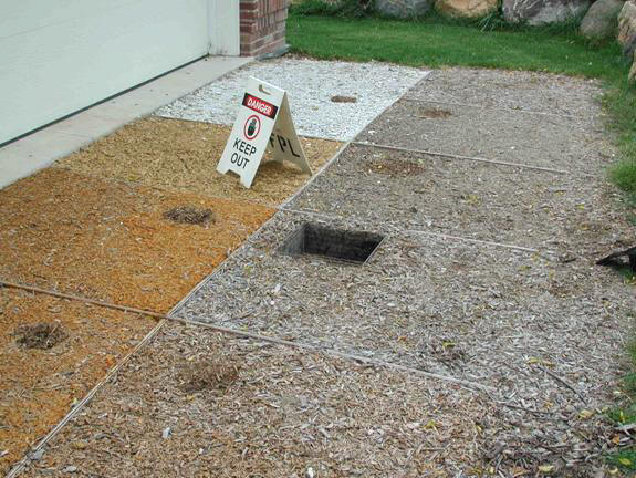
Figure 6. Each tested surface had a small portion removed following the impact test to determine density and moisture content of the layer and the EWF beneath the surface.

Figure 7. A close-up view of the archeological-type excavation done to determine the moisture profile of the E2 surface. Note the gravel is shown at the bottom of the .3m (12”) excavation.
Figure 8. A comparison of the average moisture content of the stabilized surface layers with the moisture content immediately below that surface.
Table 5. Surface layer specific gravity and moisture content of EWF under surface [text version]
| Surface | Surface layer dry specific gravity | Average moisture content of surface layer (%) | Moisture Content (%) under surface layer |
|---|---|---|---|
| A2 | .265 | 22 | 131 |
| B | .293 | 48 | 123 |
| C | .438 | 45 | 160 |
| D | .416 | 35 | 132 |
| E2 | .206 (Top 25 mm) | 24 (Top 12 mm) | 76 (sampled at 25mm) |
| F | .179 | 31 | 156 |
| G | .149 | 18 | 82 |
| H | .514 | 33 | 134 |
Moisture content measurements indicate that the bonded surface layers, on average, are not as wet (by weight) as the E2 surface (unstabilized EWF). This measurement is misleading due to the binder’s non-hygroscopic properties. However, the EWF under the stabilized surfaces would appear to be much wetter. This would lead one to presume that the binder/EWF surface layer is retarding the drying process. This in turn causes the underlying EWF to be saturated. Another representation of the moisture in the EWF is shown from the data of Table 6 and illustrated in the moisture content profile of Figure 9. The trendline fitted to the data of the moisture profile in E2 indicates that it is saturated at a depth of approximately 100 mm (4”) and continues to be saturated to the drainage bed. This is an area where additional study would yield some knowledge of the rate of decay under these very wet/saturated conditions. We have no quantified model for predicting the loss (decay) of woody material under these moisture conditions. We could easily presume development of a Resin-EWF System with reduced MC in the unbound EWF would result in a beneficial reduction of decay rates. This in-turn would then extend the life of EWF in-situ for playground surfaces.

Figure 9. Profile of moisture content through the EWF of surface E2 and a trendline fitted through the measurements.
| Surface E | Z-depth (mm) | Wet Wt. (g) | Dry Wt. (g) | MC (%) |
|---|---|---|---|---|
| E0 | 12 | 26.3 | 21.22 | 24 |
| E1 | 25 | 23.8 | 13.5 | 76 |
| E2 | 50 | 24.7 | 11.3 | 119 |
| E3 | 75 | 25.8 | 10.7 | 141 |
| E6 | 150 | 23.6 | 9.5 | 148 |
| E9 | 225 | 25.9 | 10.4 | 149 |
| E12 | 300 | 24.5 | 9.6 | 155 |
| Surface Layer | Wet Wt. (g) | Dry Wt (g) | Area (cm2) | Depth (cm) | Volume (cm3) | Dry SG | MC (%) |
|---|---|---|---|---|---|---|---|
| A | 253 | 207.5 | 156.3 | 5 | 782 | 0.265 | 22 |
| B | 339.7 | 229.3 | 156.3 | 5 | 782 | 0.293 | 48 |
| C | 367.8 | 253 | 156.3 | 3.7 | 578 | 0.438 | 45 |
| D | 219.3 | 162.6 | 156.3 | 2.5 | 391 | 0.416 | 35 |
| F | 227.4 | 173.7 | 156.3 | 6.2 | 969 | 0.179 | 31 |
| G | 170.9 | 144.6 | 156.3 | 6.2 | 969 | 0.149 | 18 |
| H | 394.2 | 297.1 | 156.3 | 3.7 | 578 | 0.514 | 33 |
1. Firmness
2. Stability
System Durability
1.The EWF under the stabilized surfaces was significantly wetter than unsurfaced
EWF.
2.Stabilized surface layers are retarding the drying process for the underlying EWF resulting in very saturated EWF.
3.Additional study should focus attention on the moisture levels and rate of decay under these surfaces which seem to exacerbate the EWF wet/saturated conditions.
It is recommended that the next phase of development should be to install larger surfaces in a working playground to evaluate accessibility and durability. The stabilizers that have met the requirements for this next phase include the polyurethanes and latex systems. We believe it best to choose one commercially available binder for each type of adhesive system. From the standpoint of their impact and accessibility performance, the polyurethane Vitriturf and the latex Soil-Sement are the best candidates. The polyurethane ReacTITE produced a hard brittle shell which aged to be even harder and would increase the injury rate for falls on the surface. The silicone AllGuard system is also rejected as it did not maintain its integrity adequately to bond EWF into a contiguous mat.
Before any recommendations for public acceptance of any candidate Resin-EWF System(s) can be made, there is a critical need for a full-scale Phase III Field Assessment to more completely understand the on-going performance and durability of any candidate Resin-EWF System(s). For Phase III a larger pad than that used in Phase II would give a better result and reduce the edge effects on the evaluation. At a minimum, a 3 x 3 meter (10 x 10 ft.) surface should be installed on a working playground being accessed regularly by children. System performance and the moisture and temperature profiles through the depth of the candidate Resin-EWF System(s) during a two-year field exposure should be carefully monitored. To identify two configurations of each of the two binder systems to install in our proposed full-scale Phase III Field Assessment, industry leaders should be consulted.
Bill Botten for guidance in initiating this phase of the Stabilized EWF concept’s development. Ted Illjes and Doug Zeager for performing the F1292 impact tests, Zeager Brothers, Inc. for donating EWF materials. Andrzej Krzysik, Benjamin Henderson, Vicki Herian, Carl Syftestad, Nancy Keen, Al Christiansen, Lloyd Currier, and other staff of the Forest Products Laboratory for their assistance during the project.
American Society for Testing and Materials. ASTM F1292 Standard Specification for Impact Attenuation of Surface Systems Under and Around Playground Equipment, ASTM, West Conshohocken,PA 19428
American Society for Testing and Materials. ASTM F1951 Standard Specification for Determination of Accessibility of Surface Systems Under and Around Playground Equipment, ASTM, West Conshohocken, PA 19428
American Society for Testing and Materials. ASTM F2075-01, Vol. 15.07.Standard Specification for engineered wood fiber. ASTM, West Conshohocken, PA 19428
ADA. 1990. Public Law 101-336. Text of the Americans with Disabilities Act, Public Law 336 of the 101st Congress, enacted July 26, 1990.
Axelson, P.W.; Chesney, D. 1999. Accessible exterior surfaces technical report. Washington, DC: United States Architectural and Transportation Barriers Compliance Board.
Laufenberg T., Krzysik, A. M., and Winandy, J. E. 2002 Improved Engineered Wood Fiber (EWF) Surfaces for Accessible Playgrounds, Final Report, Interagency Agreement 00-CO-11111124-154, Madison, WI 53726.