Published in the Federal Register on February 13, 2013.
36 CFR Part 1190
[Docket No. 2013-02]
RIN 3014-AA26
AGENCY: Architectural and Transportation Barriers Compliance Board.
ACTION: Supplemental Notice of Proposed Rulemaking.
SUMMARY: We, the Architectural and Transportation Barriers Compliance Board (Access Board), issued an advance notice of proposed rulemaking (ANPRM) announcing our intent to develop accessibility guidelines for shared used paths. Shared use paths are multi-use paths designed primarily for use by bicyclists and pedestrians, including pedestrians with disabilities, for transportation and recreation purposes. Shared use paths are physically separated from motor vehicle traffic by an open space or barrier, and are either within the highway right-of-way or within an independent right-of-way. We noted in the ANPRM that we are considering including accessibility guidelines for shared use paths in the accessibility guidelines that we are developing for sidewalks and other pedestrian facilities in the public right-of-way. We subsequently issued a notice of proposed rulemaking (NPRM) requesting comments on proposed accessibility guidelines for pedestrian facilities in the public right-of-way. The NPRM did not include specific provisions for shared use paths. We are issuing this supplemental notice of proposed rulemaking (SNPRM) to include specific provisions for shared use paths in the proposed accessibility guidelines for pedestrian facilities in the public right-of-way. The proposed accessibility guidelines would apply to the design, construction, and alteration of pedestrian facilities in the public right-of-way, including shared use paths, covered by the Americans with Disabilities Act and the Architectural Barriers Act, and would ensure that the facilities are readily accessible to and usable by individuals with disabilities.
DATES: Submit comments by May 14, 2013.
ADDRESSES: Submit comments by any of the following methods:
All comments received will be posted without change to http://www.regulations.gov, including any personal information provided.
FOR FURTHER INFORMATION CONTACT: Scott Windley, Access Board, 1331 F Street NW., Suite 1000, Washington, DC 20004-1111. Telephone (202) 272-0025 (voice) or (202) 272-0028 (TTY). E-mail address row@access-board.gov.
Table of Contents
1. Executive Summary
2. Background
3. Proposed Supplements to Proposed Accessibility Guidelines for Pedestrian Facilities in the Public Right-of-Way
4. Comparison of Proposed Technical Provisions Applicable to Shared Use Paths and AASHTO Guide
5. Conflicts Between Shared Path Users
6. Regulatory Analyses
Text of the Proposed Guidelines with Supplementary Provisions
In this preamble, "we," "us," and "our" refer to the Architectural and Transportation Barriers Compliance Board (Access Board).
This supplemental notice of proposed rulemaking (SNPRM) proposes to include specific provisions for shared use paths in the proposed accessibility guidelines for pedestrian facilities in the public right-of-way published in the Federal Register on July 26, 2011. See 76 FR 44664 (July 26, 2011). A copy of the proposed accessibility guidelines for pedestrian facilities in the public right-of-way with the specific provisions for shared use paths proposed in the SNPRM is available below.
We are required by section 502 of the Rehabilitation Act to establish and maintain accessibility guidelines for the design, construction, and alteration of facilities covered by the Americans with Disabilities Act (ADA) and the Architectural Barriers Act (ABA) to ensure that the facilities are readily accessible to and usable by individuals with disabilities. See 29 U.S.C. 792 (b) (3). The ADA covers state and local government facilities, places of public accommodation, and commercial facilities. See 42 U.S.C. 12101 et seq. The ABA covers facilities financed with federal funds. See 42 U.S.C. 4151 et seq.
We are issuing the SNPRM in response to public comments on separate rulemakings to develop accessibility guidelines for trails and other outdoor developed areas, and for sidewalks and other pedestrian facilities in the public right-of-way. The comments noted that shared use paths are distinct from trails and sidewalks, and recommended that we develop accessibility guidelines for shared use paths. As defined in the SNPRM, shared use paths are multi-use paths designed primarily for use by bicyclists and pedestrians, including pedestrians with disabilities, for transportation and recreation purposes. Shared use paths are physically separated from motor vehicle traffic by an open space or barrier, and are either within the highway right-of-way or within an independent right-of-way.
As noted above, the SNPRM would include specific provisions for shared use paths in the proposed accessibility guidelines for pedestrian facilities in the public right-of-way. The proposed accessibility guidelines for pedestrian facilities in the public right-of-way would require pedestrian access routes to be provided within pedestrian circulation paths located in the public right-of-way, and would establish proposed technical provisions for the width, grade, cross slope, and surface of pedestrian access routes. See R204.2 and R302. Where existing pedestrian circulation paths are altered and existing physical constraints make it impracticable for the altered paths to fully comply with the proposed technical provisions, compliance would be required to the extent practicable. See R202.3.1.
The SNPRM would:
The SNPRM is consistent with the design criteria for shared used paths in the American Association of State Highway and Transportation Officials (AASHTO) "Guide for the Development of Bicycle Facilities" (2012) (hereinafter referred to as the "AASHTO Guide"). The SNPRM is not expected to increase the cost of constructing shared use paths for state and local government jurisdictions that use the AASHTO Guide.
As discussed in the preamble to the proposed accessibility guidelines for pedestrian facilities in the public right-of-way, other federal agencies are required to adopt accessibility standards for the design, construction, and alteration of facilities covered by the ADA and ABA that are consistent with our accessibility guidelines. When the other federal agencies adopt accessibility standards for the design, construction, and alteration of pedestrian facilities in the public right-of-way, including shared use paths, covered by the ADA and ABA, compliance with the standards is mandatory.
We are conducting separate rulemakings to develop accessibility guidelines for trails and other outdoor developed areas, and for sidewalks and other pedestrian facilities in the public right-of-way.
We issued a notice of proposed rulemaking (NPRM) requesting comments on proposed accessibility guidelines for trails and other outdoor developed areas in 2007. See 72 FR 34074 (June 20, 2007). A trail would be defined for purposes of these accessibility guidelines as a pedestrian route developed primarily for outdoor recreational purposes. A pedestrian route developed primarily to connect elements, spaces, or facilities within a site is not a trail.
We requested comments on draft accessibility guidelines for sidewalks and other pedestrian facilities in the public right-of-way in 2002 and 2005. See 67 FR 41206 (June 17, 2002); and 70 FR 70734 (November 23, 2005). These accessibility guidelines would adopt the definition of sidewalk in the Manual on Uniform Traffic Control Devices (MUTCD). The MUTCD (2009) defines a sidewalk as the portion of a street between the curb line, or the lateral line of a roadway, and the adjacent property line or on easements of private property that is paved or improved and intended for use by pedestrians.
Public comments on these rulemakings noted that shared use paths are distinct from trails and sidewalks in that they are used by bicyclists and pedestrians, including pedestrians with disabilities, for transportation and recreation purposes. The comments recommended that we develop accessibility guidelines for shared use paths. On March 28, 2011, we issued an advance notice of proposed rulemaking (ANPRM) announcing our intent to develop accessibility guidelines for shared use paths, and requested comments on a definition and draft technical provisions for shared use paths. See 76 FR 17064 (March 28, 2011). We noted in the ANPRM that we are considering including accessibility guidelines for shared use paths in the accessibility guidelines for pedestrian facilities in the public right-of-way since state and local transportation departments are the principal entities that design and construct shared use paths, and many of the draft technical provisions for shared use paths in the ANPRM are the same as those in the draft accessibility guidelines for pedestrian facilities in the public right-of-way (e.g., curb ramps and blended transitions, and detectable warning surfaces).
On July 26, 2011, we issued a NPRM requesting comments on proposed accessibility guidelines for pedestrian facilities in the public right-of-way. See 76 FR 44664 (July 26, 2011). The NPRM did not include specific provisions for shared use paths. The comment period on the NPRM ended on November 23, 2011. The comment period was reopened on December 5, 2011 to allow additional time for the public to submit comments. See 76 FR 75844 (December 5, 2011). The additional comment period ended on February 2, 2012.
3. Proposed Supplements to Proposed Accessibility Guidelines for Pedestrian Facilities in the Public Right-of-Way
We are issuing this SNPRM to include specific provisions for shared use paths in the proposed accessibility guidelines for pedestrian facilities in the public right-of-way published in the Federal Register on July 26, 2011. See 76 FR 44664 (July 26, 2011). The proposed accessibility guidelines for pedestrian facilities in the public right-of-way will be codified as an appendix to 36 CFR part 1190. The SNPRM would supplement the following sections of the proposed accessibility guidelines for pedestrian facilities in the public right-of-way: R105.5 Defined Terms; R204 and R302 Pedestrian Access Routes; R210 Protruding Objects; R218 Doors, Doorways, and Gates; and R304 Curb Ramps and Blended Transitions. The proposed supplements to these sections are set forth below.
R105.5 Defined Terms.
Shared Use Path
The SNPRM would add a proposed definition of shared use path in R105.5 to read as follows:
Shared Use Path. A multi-use path designed primarily for use by bicyclists and pedestrians, including pedestrians with disabilities, for transportation and recreation purposes. Shared use paths are physically separated from motor vehicle traffic by an open space or barrier, and are either within the highway right-of-way or within an independent right-of-way.
The proposed definition is based on the AASHTO Guide, which defines a shared use path as a bikeway physically separated from motor vehicle traffic by an open space or barrier, and either within the highway right-of-way or within an independent right of way. The AASHTO Guide notes that pedestrians, including pedestrians with disabilities, also use shared use paths and that they can serve transportation and recreation purposes. See AASHTO Guide, 5.1 Introduction. The U.S. Department of Transportation, Federal Highway Administration (FHWA) defines a shared use path similar to the AASHTO Guide.1 State transportation departments also define shared use paths similar to the AASHTO Guide.2
As noted in the AASHTO Guide, the primary factor that distinguishes shared use paths and sidewalks is the intended user. Shared use paths are designed for use by bicyclists and pedestrians, including pedestrians with disabilities. Sidewalks are designed for use by pedestrians, including pedestrians with disabilities, and are not intended for use by bicyclists. See AASHTO Guide, 5.2.2, Shared Use Paths Adjacent to Roadways (Sidepaths).
Public Right-of-Way
The SNPRM would revise the proposed definition of public right-of-way in R105.5 to read as follows:
Public Right-of-Way. Public land acquired for or dedicated to transportation purposes, or other land where there is a legally established right for use by the public for transportation purposes.
The NPRM proposed to define public right-of-way as public land or property, usually in interconnected corridors, that is acquired for or dedicated to transportation purposes. Some shared use paths may cross private land. In these situations, an easement or other legal means is used to establish a right for the public to use the portion of the land that the shared use path crosses for transportation purposes. The SNPRM would revise the proposed definition of public right-of-way to include these situations.
R204 and R302 Pedestrian Access Routes
The SNPRM would revise these sections relating to pedestrian access routes.
R204.2 Pedestrian Circulation Paths
The SNPRM would revise R204.2 to read as follows:
R204.2 Pedestrian Circulation Paths. A pedestrian access route shall be provided within pedestrian circulation paths located in the public right-of-way. The pedestrian access route shall connect to accessible elements, spaces, and facilities required by this document and to accessible routes required by section 206.2.1 of appendix B to 36 CFR part 1191 or section F206.2.1 of appendix C to 36 CFR 1191 that connect building and facility entrances to public streets and sidewalks.
As proposed in the NPRM, R204.2 would require a pedestrian access route to be provided within sidewalks and other pedestrian circulation paths located in the public right-of-way. The NPRM proposed to define a pedestrian circulation path as a prepared exterior or interior surface provided for pedestrian travel in the public right-of-way. See R105.5. Sidewalks and shared use paths are types of pedestrian circulation paths. As revised by the SNPRM, the term "pedestrian circulation paths" in R204.2 includes sidewalks and shared use paths.
R302.3 Continuous Width
The SNPRM would revise R302.3 to read as follows:
R302.3 Continuous Width. Except as provided in R302.3.1 and R302.3.2, the continuous clear width of pedestrian access routes shall be 1.2 m (4.0 ft) minimum, exclusive of the width of the curb.
R302.3.1 Medians and Pedestrian Refuge Islands. The clear width of pedestrian access routes within medians and pedestrian refuge islands shall be 1.5 m (5.0 ft) minimum.
R302.3.2 Shared Use Paths. A pedestrian access route shall be provided for the full width of a shared use path.
As proposed in the NPRM, R302.3 would require pedestrian access routes to be 4 feet wide minimum, except R302.3.1 would require pedestrian access routes within medians and pedestrian refuge islands to be 5 feet wide minimum to allow for passing space.
The SNPRM would add a new provision at R302.3.2 that would require a pedestrian access route to be provided for the full width of a shared use path since shared use paths are typically two-directional and path users travel in each direction on the right hand side of the path, except to pass. The AASHTO Guide recommends that two-directional shared use paths should be 10 feet wide minimum. Where shared use paths are anticipated to serve a high percentage of pedestrians and high user volumes, the AASHTO Guide recommends that the paths should be 11 to 14 feet wide to enable a bicyclist to pass another path user travelling in the same direction, at the same time a path user is approaching from the opposite direction. In certain very rare circumstances, the AASHTO Guide permits the width of shared use paths to be reduced to 8 feet. See AASHTO Guide, 5.2.1 Width and Clearance.
R302.5 Grade
The SNPRM would revise R302.5 to read as follows:
R302.5 Grade. The grade of pedestrian access routes shall comply with R302.5.
R302.5.1 Within Street or Highway Right-of-Way. Except as provided in R302.5.3, where pedestrian access routes are contained within a street or highway right-of-way, the grade of pedestrian access routes shall not exceed the general grade established for the adjacent street or highway.
R302.5.2 Not Within Street or Highway Right-of-Way. Where pedestrian access routes are not contained within a street or highway right-of-way, the grade of pedestrian access routes shall be 5 percent maximum.
R302.5.3 Within Pedestrian Street Crossings. Where pedestrian access routes are contained within a pedestrian street crossing, the grade of pedestrian access routes shall be 5 percent maximum.
R302.5.4 Physical Constraints. Where compliance with R302.5.1 or R302.5.2 is not practicable due to existing terrain or infrastructure, right-of-way availability, a notable natural feature, or similar existing physical constraints, compliance is required to the extent practicable.
R302.5.5 Regulatory Constraints. Where compliance with R302.5.1 or R302.5.2 is precluded by federal, state, or local laws the purpose of which is to preserve threatened or endangered species; the environment; or archaeological, cultural, historical, or significant natural features, compliance is required to the extent practicable.
As proposed in the NPRM, R302.5 would require the grade of pedestrian access routes contained within a street or highway right-of-way, except at pedestrian street crossings, to not exceed the general grade established for the adjacent street or highway; and the grade of pedestrian access routes not contained within a street or highway right-of-way to be 5 percent maximum. R302.5.1 would require the grade of pedestrian access routes contained within a pedestrian street crossing to be 5 percent maximum.
The SNPRM would renumber R302.5 to include a general provision in R302.5; the specific provision for the grade of pedestrian access routes contained within a street or highway right-of-way in R302.5.1; the specific provision for the grade of pedestrian access routes not contained within a street or highway right-of-way in R302.5.2; and the specific provision for the grade of pedestrian access routes contained within a pedestrian street crossing in R302.5.3.
The SNPRM would add new provisions at R302.5.4 and R302.5.5 that would require compliance with the grade provisions in R302.5.1 or R302.5.2 to the extent practicable where compliance is not practicable due to physical constraints and where compliance is precluded by regulatory constraints. We propose to add these new provisions in response to public comments on the ANPRM, which included draft technical provisions for grade similar to those proposed in the R302.5. The comments noted that physical or regulatory constraints may prevent full compliance with the grade provisions. Physical constraints would include existing terrain or infrastructure, right-of-way availability, a notable natural feature, or similar existing physical constraints. Regulatory constraints would include federal, state, or local laws the purpose of which is to preserve threatened or endangered species; the environment; or archaeological, cultural, historical, or significant natural features.
The proposed provisions are consistent with the AASHTO Guide. The AASHTO Guide recommends that the grade of a shared use path should not exceed 5 percent; but, where the path is adjacent to a roadway with a grade that exceeds 5 percent, the grade of the path should be less than or equal to the roadway grade. The AASHTO Guide notes that grades steeper than 5 percent are undesirable because ascents are difficult for many path users, and the descents can cause some path users to exceed the speeds at which they are competent or comfortable. See AASHTO Guide, 5.2.7 Grade.
R210 Protruding Objects
The SNPRM would revise R210 to read as follows:
R210.1 General. Protruding objects shall comply with the applicable requirements in R210.
R210.2 Pedestrian Circulation Paths Other Than Shared Use Paths. Objects along or overhanging any portion of a pedestrian circulation path other than a shared use path shall comply with R402 and shall not reduce the clear width required for pedestrian access routes.
R210.3 Shared Use Paths. Objects shall not overhang or protrude into any portion of a shared use path at or below 2.4 m (8.0 ft) measured from the finish surface.
As proposed in the NPRM, R210 would require objects along or overhanging any portion of a pedestrian circulation path to comply with the proposed technical provisions for protruding objects in R402 and to not reduce the clear width required for pedestrian access routes.
The SNPRM would renumber R210 to include a general provision in R210.1 and a specific provision for pedestrian circulation paths other than shared use paths in R210.2 that would require objects along or overhanging any portion of the path to comply with the proposed technical provisions for protruding objects in R402 and to not reduce the clear width required for pedestrian access routes, as proposed in the NPRM.
The SNPRM would add a new provision for shared use paths at R210.3 that would prohibit objects from overhanging or protruding into any portion of a shared use path at or below 8 feet measured from the finish surface.
The proposed provision for shared used paths is consistent with the AASHTO Guide. The AASHTO Guide recommends 10 feet vertical clearance along shared use paths, and 8 feet minimum vertical clearance in constrained areas. The AASHTO Guide recommends that fixed objects should not be permitted to protrude within the vertical or horizontal clearance of a shared use path. See AASHTO Guide, 5.2.1 Width and Clearance.
R218 Doors, Doorways, and Gates
The SNPRM would revise R218 to read as follows:
R218 Doors, Doorways, and Gates. Except for shared use paths, doors, doorways, and gates provided at pedestrian facilities shall comply with section 404 of Appendix D to 36 CFR to 36 CFR part 1191.
The SNPRM would not apply the technical provisions for doors, doorways, and gates referenced in R218 to shared use paths to avoid conflicts with the AASHTO Guide. The AASHTO Guide does not recommend the use of gates or other barriers to prevent unauthorized motor vehicle entry to shared use paths because gates and barriers create permanent obstacles to path users. The AASHTO Guide recommends alternative methods to control unauthorized motor vehicle entry to shared use paths, including posting regulatory signs prohibiting motor vehicle entry and targeted surveillance and enforcement. Where there is a documented history of unauthorized entry by motor vehicles despite the use of alternative methods to control such entry, the need for bollards or other vertical barriers may be justified. The AASHTO Guide includes recommended designs for bollards where justified. The AASHTO Guide recommends the use of one bollard in the center of the shared use path. Where more than one bollard is used, the AASHTO Guide recommends an odd number of posts spaced at 6 feet. The AASHTO Guide does not recommend two posts since they direct opposing path users toward the middle, creating conflict and the possibility of a head-on collision. See AASHTO Guide, 5.3.5 Other Intersection Treatments.
R304 Curb Ramps and Blended Transitions
The SNPRM would revise R304.5.1 to read as follows:
R304.5.1 Width. The width of curb ramps and blended transitions shall comply with 304.5.1.1 or 304.5.1.2, as applicable. If provided, flared sides of curb ramp runs and blended transitions shall be located outside the width of the curb ramp run or blended transition.
R304.5.1.1 Pedestrian Circulation Paths Other Than Shared Use Paths. In pedestrian circulation paths other than shared use paths, the clear width of curb ramp runs, blended transitions, and turning spaces shall be 1.2 m (4.0 ft) minimum.
R304.5.1.2 Shared Use Paths. In shared use paths, the width of curb ramps runs and blended transitions shall be equal to the width of the shared use path.
As proposed in the NPRM, R304.5.1 would require the clear width of curb ramp runs (excluding flared sides), blended transitions, and turning spaces to be 4 feet minimum.
The SNPRM would renumber R304.5.1 to include a general provision in R304.5.1 that would clarify that if flared sides are provided at curb ramps and blended transitions, the flared sides are to be located outside the width of the curb ramp run or blended transition; and a specific provision for pedestrian circulation paths other than shared use paths in R304.5.1.1 that would require the clear width of curb ramp runs, blended transitions, and turning spaces to be 4 feet minimum, as proposed in the NPRM.
The SNPRM would add a new provision for shared use paths at R304.5.1.2 that would require the width of curb ramps runs and blended transitions to be equal to the width of the shared use path.
The proposed provision for shared used paths is consistent with the AASHTO Guide. The AASHTO Guide recommends that where curb ramps are provided on shared use paths, the curb ramps should extend the full width of the path, not including any flared sides. See AASHTO Guide, 5.3.5 Other Intersection Treatments.
4. Comparison of Proposed Technical Provisions Applicable to Shared Use Paths and AASHTO Guide
The proposed technical provisions applicable to shared used paths in the proposed accessibility guidelines for pedestrian facilities in the public right-of-way, as supplemented by the SNPRM, and the design criteria for shared use paths in the AASHTO Guide are compared in the table below.
Proposed Accessibility Guidelines for Pedestrian Facilities |
AASHTO Guide for the
Development of Bicycle Facilities (2012)
Chapter 5: Design of Shared Use Paths |
|---|---|
R302.3.2 Shared Use Paths. A pedestrian access route shall be provided for the full width of a shared use path. |
5.2.1 Width and Clearance The minimum paved width for a two-directional shared use path is 10 ft (3.0 m). . . . In very rare circumstances, a reduced width of 8 ft (2.4 m) may be used . . . . Wider pathways, 11 to 14 ft (3.4 to 4.2 m) are recommended in locations that are anticipated to serve a high percentage of pedestrians (30 percent or more of the total pathway volume) and higher user volumes (more than 300 total users in the peak hour). |
R302.5 Grade. The grade of pedestrian access routes shall comply with R302.5. R302.5.1 Within Street or Highway Right-of-Way. Except as provided in R302.5.3, where pedestrian access routes are contained within a street or highway right-of-way, the grade of pedestrian access routes shall not exceed the general grade established for the adjacent street or highway. R302.5.2 Not Within Street or Highway Right-of-Way. Where pedestrian access routes are not contained within a street or highway right-of-way, the grade of pedestrian access routes shall be 5 percent maximum. R302.5.3 Within Pedestrian Street Crossings. Where pedestrian access routes are contained within a pedestrian street crossing, the grade of pedestrian access routes shall be 5 percent maximum. R302.5.4 Physical Constraints. Where compliance with R302.5.1 or R302.5.2 is not practicable due to existing terrain or infrastructure, right-of-way availability, a notable natural feature, or similar existing physical constraints, compliance is required to the extent practicable. R302.5.5 Regulatory Constraints. Where compliance with 302.5.1 or 302.5.2 is precluded by federal, state, or local laws the purpose of which is to preserve threatened or endangered species; the environment; or archaeological, cultural, historical, or significant natural features, compliance is required to the extent practicable.
|
5.2.7 Grade The maximum grade of a shared use path adjacent to a roadway should be 5 percent, but the grade should generally match the grade of the adjacent roadway. Where a shared use path runs along a roadway with a grade that exceeds 5 percent, the sidepath grade may exceed 5 percent but must be less than or equal to the roadway grade. Grades on shared use paths in independent rights-of-way should be kept to a minimum. Grades steeper than 5 percent are undesirable because the ascents are difficult for many path users, and the descents can cause some users to exceed the speeds at which they are competent or comfortable. . . . Grades on paths in independent rights-of-way should also be limited to 5 percent maximum. |
R302.6 Cross Slope. Except as provided in R302.6.1 and R302.6.2, the cross slope of pedestrian access routes shall be 2 percent maximum. R302.6.1 Pedestrian Street Crossings Without Yield or Stop Control. Where pedestrian access routes are contained within pedestrian street crossings without yield or stop control, the cross slope of the pedestrian access route shall be 5 percent maximum. R302.6.2 Midblock Pedestrian Street Crossings. Where pedestrian access routes are contained within midblock pedestrian street crossings, the cross slope of the pedestrian access route shall be permitted to equal the street or highway grade.
|
5.2.5 Cross Slope As described in the previous section, 1 percent cross slopes are recommended on shared use paths, to better accommodate people with disabilities and to provide enough slope to convey surface drainage in most situations. |
R302.7 Surfaces. The surfaces of pedestrian access routes and elements and spaces required to comply with R302.7 that connect to pedestrian access routes shall be firm, stable, and slip resistant and shall comply with R302.7. R302.7.1 Vertical Alignment. Vertical alignment shall be generally planar within pedestrian access routes (including curb ramp runs, blended transitions, turning spaces, and gutter areas within pedestrian access routes) and surfaces at other elements and spaces required to comply with R302.7 that connect to pedestrian access routes. Grade breaks shall be flush. Where pedestrian access routes cross rails at grade, the pedestrian access route surface shall be level and flush with the top of rail at the outer edges of the rails, and the surface between the rails shall be aligned with the top of rail. R302.7.2 Vertical Surface Discontinuities. Vertical surface discontinuities shall be 13 mm (0.5 in) maximum. Vertical surface discontinuities between 6.4 mm (0.25 in) and 13 mm (0.5 in) shall be beveled with a slope not steeper than 50 percent. The bevel shall be applied across the entire vertical surface discontinuity. R302.7.3 Horizontal Openings. Horizontal openings in gratings and joints shall not permit passage of a sphere more than 13 mm (0.5 in) in diameter. Elongated openings in gratings shall be placed so that the long dimension is perpendicular to the dominant direction of travel. R302.7.4 Flangeway Gaps. Flangeway gaps at pedestrian at-grade rail crossings shall be 64 mm (2.5 in) maximum on non-freight rail track and 75 mm (3 in) maximum on freight rail track.
|
5.2.9 Surface Structure Hard, all-weather pavement surfaces are generally preferred over those of crushed aggregate, sand, clay, or stabilized earth. . . . Unpaved surfaces may be appropriate on rural paths, where the intended use of the path is primarily recreational, or as a temporary measure to open a path before funding is available for paving. Unpaved pathways should be constructed of materials that are firm and stable. . . . It is important to construct and maintain a smooth riding surface on shared use paths. . . . Utility covers (i.e., manholes) and bicycle-compatible drainage grates should be flush with the surface of the pavement on all sides. . . . Railroad crossings should be smooth and should be designed at an angle between 60 and 90 degrees to the direction of travel to minimize the possibility of falls. |
R210.3 Shared Use Paths. Objects shall not overhang or protrude into any portion of a shared use path at or below 2.4 m (8.0 ft) measured from the finish surface.
|
5.2.1 Width and Clearance The desirable vertical clearance to obstructions is 10 ft (3.0 m). Fixed objects should not be permitted to protrude within the vertical or horizontal clearance of a shared use path. The recommended minimum vertical clearance that can be used in constrained areas is 8 ft (2.4 m).
|
R304.5.1.2 Shared Use Paths. In shared use paths, the width of curb ramps runs and blended transitions shall be equal to the width of the shared use path. R305.1.4 Size. Detectable warning surfaces shall extend 610 mm (2.0 ft) minimum in the direction of pedestrian travel. At curb ramps and blended transitions, detectable warning surfaces shall extend the full width of the ramp run (excluding any flared sides).
|
5.3.5 Other Intersection Treatments The opening of a shared use path at the roadway should be at least the same width as the shared use path itself. If a curb ramp is provided, the ramp should be the full width of the path, not including any flared sides if utilized. . . . Detectable warnings should be placed across the full width of the ramp. |
5. Conflicts Between Shared Path Users
Public comments submitted in response to the ANPRM expressed concern about the risk of collisions between pedestrians who are blind or have low vision and bicyclists who pass them too closely at fast speeds, and at intersections where a shared use path crosses another shared use path or a sidewalk. According to the AASHTO Guide, the 85th percentile speed for recreational bicyclists is 18 miles per hour. See AASHTO Guide, 5.2.4 Design Speed. The comments noted that bicycles are relatively quiet and pedestrians who are blind or have low vision may not be aware when bicyclists are approaching and passing them or crossing their path at intersections. Pedestrians with other disabilities may also have limited awareness of approaching bicyclists. For example, individuals who are deaf or hard of hearing may not be aware of a bicycle approaching from behind even when riders indicate their presence audibly. Individuals with limited mobility who may be alert to bicyclists may find it difficult to move aside in time to avoid collision. The comments recommended that traffic on shared use paths be regulated and strictly enforced in order to protect pedestrians. For example, a comment stated that bicyclists should be required to always yield to pedestrians. The comments also recommended design solutions to avoid conflicts between users, including separate pathways for pedestrians and bicyclists; and detectable warning surfaces at intersections where a shared use path crosses another shared use path or a sidewalk. These design solutions are discussed below.
Separate Pathways for Pedestrians and Bicyclists
An organization representing individuals who are blind and have low-vision stated that "all shared use paths present an unacceptable safety risk to blind or visually impaired pedestrians unless there is a clear separation between pedestrians and other motorized and non-motorized vehicles including bicyclists." The comments noted that path users cannot be expected to always follow the "rules of the road" and suggested that if paths cannot be physically separated that lanes for pedestrians and other users should be marked tactilely. An organization of educators and rehabilitation professionals who work with individuals who are blind suggested that blind pedestrians may have considerable difficulty maintaining the course, particularly on two-directional shared use paths where all users are expected to travel on the right hand side of the path in each direction and bicyclists pass pedestrians and slower moving path users on their left hand side. In addition to the recommendation to physically separate pedestrians and bicyclists, the comments suggested that it may be necessary to separate the two directions of travel within each pathway, particularly on busy paths. The comments, however, acknowledged that determining what volume of users should require two-directional separation would be a challenge.
The AASHTO Guide makes a number of recommendations to minimize conflicts between pedestrians and bicyclists. These recommendations include required sight triangles to ensure that bicyclists have the needed yielding distance to avoid conflicts, and additional width around horizontal curves to allow safe distance between users. See AASHTO 5.2.8, Stopping Sight Distance. The AAHSTO Guide also recommends use of a centerline stripe within a path to provide directional separation and to indicate when passing is permitted. For paths with "extremely heavy volume", the AASHTO Guide recommends two alternatives for segregation of pedestrians and bicyclists. The first option is to provide separate lanes within a single path; pedestrians have a bidirectional lane and bicyclists have two one-directional lanes. Such separation is not recommended unless a minimum path width of 15 feet can be provided (10 feet for bicycles and 5 feet for pedestrians). A second alternative is to physically separate user groups, particularly where the pathway volume is "extremely heavy" and where sites and settings, such as one that constricts the path width, necessitate divergent pathways. Physically separated pathways also are recommended where the origins and destinations of pedestrians and bicyclists differ. The AAHSTO Guide notes that both alternatives (lane separation and physical separation) may not be effective unless the volume of bicycle traffic is sufficient to discourage pedestrians from encroaching into the bicycle lanes and that these solutions will not necessarily be needed for the full length of a shared use path. See AASHTO Guide, 5.2.1 Width and Clearance.
We agree with the comments that physical separation between pedestrians and other users would likely render shared use paths safer for, and more accessible to, individuals with disabilities and others. However, the AASHTO Guide does not recommend physical separation of user groups unless the traffic volume or other considerations make separate pathways necessary. The AASHTO Guide provides little guidance regarding methods for determining the point at which traffic volume or other considerations would justify separation of the pathways. In the absence of any data on which to base such a requirement, we are not proposing to require physically separated pathways for pedestrians and bicyclists. The impact of such a requirement if applied to the full length of all shared use paths would likely result in many not being constructed due to the increased costs associated with more land and the need to engineer and construct two pathways instead of one.
The comments suggested that enhanced signage and warnings, including audible signs and tactile pavement markings would improve the ability of blind pedestrians to remain within their lanes. In Great Britain, tactile pavement markings are used to indicate bicycle and pedestrian lanes. A ladder pattern is used to indicate the start and end of the pedestrian lane; a tramline pattern is used to indicate the start and end of the bicycle lane; and a tactile dividing line is used to indicate the separation between the lanes.3 At least one U.S. manufacturer makes tactile pavement markings for shared use paths. We request comments on whether tactile pavement markings have been used on any shared use paths in the U.S. and the experience with such markings. We also request comments on other design solutions to reduce potential conflicts between pedestrians who are blind or have low vision and bicyclists. Comments should include factors that would make such solutions necessary.
We are considering including an advisory section in the final accessibility guidelines on separate pathways for pedestrians and bicyclists. Advisory sections are not mandatory requirements but provide guidance for entities who want to exceed the minimum requirements for accessible design. We request comments on information to include in the advisory section.
Detectable Warning Surfaces at Shared Use Path Intersections
Detectable warning surfaces consist of small truncated domes that are integral to a walking surface and that are detectable underfoot. The proposed accessibility guidelines for pedestrian facilities in the public right-of-way would require the use of detectable warning surfaces to indicate the boundary between a pedestrian route and a vehicular route where there is a curb ramp or blended transition; and the boundary of passenger boarding platforms at transit stops for buses and rail vehicles and at passenger boarding and alighting areas at sidewalk or street level transit stops for rail vehicles. See R208 and R305.
Because pedestrians who are blind would not be aware of bicyclists approaching from the left or right hand side at intersections, we are considering including a requirement in the final accessibility guidelines to provide detectable warning surfaces where a shared use path intersects another shared use path or a sidewalk to indicate the boundaries where bicyclists may be crossing the intersection. The edge of the detectable warning surface would be installed between 6 inches minimum and 12 inches maximum from the edge of the intersecting segments of the shared use paths and sidewalks. The detectable warning surface would extend 2 feet minimum in the direction of pedestrian travel and the full width of the intersecting segments. We request comments on this issue.
We prepared a preliminary regulatory assessment discussing the cost and benefits of the proposed accessibility guidelines for pedestrian facilities in the public right-of-way and an initial regulatory flexibility analysis of the impacts on small governmental jurisdictions with a population of less than 50,000 when the NPRM was issued. These regulatory analyses are available on our website at: http://www.access-board.gov/prowac/.
There is no database available on the number of shared use paths in the United States. AASHTO surveyed five state transportation departments when preparing comments on the ANPRM. The responding departments reported approximately 1,500 to 3,000 miles of existing shared use paths in their states. The Alliance for Biking and Walking surveyed more than 50 large cities about their bicycle and pedestrian facilities.4 The average number of miles of existing shared use paths per city was 70 miles, and ranged from 3.1 miles in Milwaukee to 328 miles in New York City. The cities used federal funds to construct many of the shared use paths.
As discussed above, the proposed technical provisions applicable to shared use paths are consistent with the AASHTO Guide. State and local government entities that design and construct shared use paths generally use the AASHTO Guide. The SNPRM is not expected to increase the costs of constructing shared use paths for state and local government entities that use the AASHTO Guide.
We request comments on the following to assess the impacts of the SNPRM:
List of Subjects in 36 CFR Part 1190
Buildings and facilities, Civil rights, Individuals with disabilities, Transportation.
Susan Brita,
Chair.
1 The FHWA defines a shared use path as a multi-use trail or path physically separated from motorized vehicular traffic by an open space or barrier, either within the highway right-of-way or within an independent right of way, and usable for transportation purposes. The FHWA definition of shared use path is available at: http://www.fhwa.dot.gov/environment/bicycle_pedestrian/guidance/design_guidance/freeways.cfm.
2 For example, the Washington State Department of Transportation Design Manual (July 2012) defines a shared use path as a facility physically separated from motorized vehicular traffic within the highway right-of-way or on an exclusive right-of-way with minimal cross flow by motor vehicles. The Washington State Department of Transportation Design Manual is available at: http://www.wsdot.wa.gov/Publications/Manuals/M22-01.htm.
3 Department of Transport, "Tactile Markings for Segregated Shared Use by Cyclists and Pedestrians" [available at: http://www.ukroads.org/webfiles/TAL%204-90%20Tactile%20Markings%20for%20Segregated%20Shared%20Use.pdf]; Department for Transport, "Guidance on the Use of Tactile Paving Surfaces, "Chapter 5 - Segregated Shared Cycle Track/Footway Surface and Central Delineator Strip [available at: http://www.dft.gov.uk/publications/guidance-on-the-use-of-tactile-paving-surfaces/]; and Department of Transport," Shared Use Routes for Pedestrians and Cyclists," Chapter 6 - General Design Considerations, 6.18 and 6.19 [available at: http://assets.dft.gov.uk/publications/ltn-01-12/shared-use-routes-for-pedestrians-and-cyclists.pdf].
4 Alliance for Biking and Walking, "Bicycling and Walking in the United States 2012 Benchmarking Report." The report is available at: http://www.peoplepoweredmovement.org/site/.
Note: Supplementary provisions are noted below in bold and unshaded boxes.
PART 1190 –ACCESSIBILITY GUIDELINES FOR PEDESTRIAN FACILITIES IN THE PUBLIC RIGHT-OF-WAY
Sec.
1190.1 Accessibility guidelines.
Appendix to part 1190 – Accessibility Guidelines for Pedestrian Facilities in the Public Right-of-Way
Authority: 29 U.S.C. 792 and 42 U.S.C. 12204.
§ 1190.1 Accessibility Guidelines.
The accessibility guidelines for pedestrian facilities in the public right-of-way are set forth in the appendix to this part. When the guidelines are adopted, with or without additions and modifications, as accessibility standards in regulations issued by other federal agencies implementing the Americans with Disabilities Act, Section 504 of the Rehabilitation Act, and the Architectural Barriers Act, compliance with the accessibility standards is mandatory. A copy of the guidelines with figures is available on the Access Board website at: http://www.access-board.gov/prowac/nprm.htm. Except for the International Symbol of Accessibility in Figure R411, which is included in the appendix to this part, the figures are for illustration purposes only and do not establish requirements.
Appendix to Part 1190 –Accessibility Guidelines for Pedestrian Facilities in the Public Right-of-Way
CHAPTER R1: APPLICATION AND ADMINISTRATION
R101 Purpose
R101.1 General. This document contains scoping and technical requirements to ensure that facilities for pedestrian circulation and use located in the public right-of-way are readily accessible to and usable by pedestrians with disabilities. Compliance with this document is mandatory when required by regulations issued by federal agencies that include accessibility standards for the design, construction, and alteration of pedestrian facilities in the public right-of-way.
Advisory R101.1 General. Sections marked as "advisory" contain advisory information related to the preceding section. Advisory sections do not establish mandatory requirements. Some advisory sections reference related mandatory requirements to alert readers about those requirements. |
R101.2 Effect on Existing Facilities. This document does not address existing facilities unless the facilities are included within the scope of an alteration undertaken at the discretion of a covered entity.
Advisory R101.2 Effect on Existing Facilities. The Department of Justice regulations implementing Title II of the Americans with Disabilities Act contain requirements for state and local governments regarding program accessibility and existing facilities. See 28 CFR 35.150. The Department of Transportation regulations implementing Section 504 of the Rehabilitation Act also contain requirements for recipients of federal financial assistance from the Department regarding compliance planning. See 49 CFR 27.11 (c). |
R102 Equivalent Facilitation. The use of alternative designs, products, or technologies that result in substantially equivalent or greater accessibility and usability than the requirements in this document is permitted.
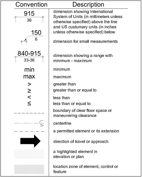
R103 Conventions
R103.1 Conventional Industry Tolerances. Dimensions are subject to conventional industry tolerances except where dimensions are stated as a range.
Advisory R103.1.1 Conventional Industry Tolerances. Conventional industry tolerances include tolerances for field conditions and tolerances that may be a necessary consequence of a particular manufacturing process. Conventional industry tolerances do not apply to design work. |
R103.2 Calculation of Percentages. Where the required number of elements or facilities to be provided is determined by calculations of ratios or percentages and remainders or fractions result, the next greater whole number of such elements or facilities shall be provided. Where the determination of the required size or dimension of an element or facility involves ratios or percentages, rounding down for values less than one half is permitted.
R103.3 Units of Measurement. Measurements are stated in metric and U.S. customary units. The values stated in each system (metric and U.S. customary units) may not be exact equivalents, and each system shall be used independently of the other.
Advisory R103.3 Units of Measurement. Users should work entirely within one system of measurement, either metric or U.S. customary units. Combining values from the two systems may result in non-compliance. |
Figure R103 Graphic Convention for Figures
R104 Referenced Standards
R104.1 Incorporation by Reference. The specific editions of the standards listed in R104.2 are incorporated by reference in this document and are part of the requirements to the prescribed extent of each such reference. The Director of the Federal Register has approved the standards for incorporation by reference in accordance with 5 U.S.C. 552(a) and 1 CFR part 51. Copies of the referenced standards may be inspected at the Access Board, 1331 F Street, NW, Suite 1000, Washington, DC 20004; or at the National Archives and Records Administration (NARA). For information on the availability of the referenced standards at NARA, call (202) 741-6030, or go to: http://www.archives.gov/federal_register/code_of_federal_regulations/ibr_locations.html.
R104.2 MUTCD. The portions of the Manual on Uniform Traffic Control Devices for Streets and Highways (MUTCD), 2009 Edition, that are incorporated by reference in this document consist of definitions (see R105.2) and standard statements, as defined in section 1A.13 of the MUTCD (see R205, R209, and R306.3). Guidance, option, and support statements, as defined in section 1A.13 of the MUTCD, shall be used to assist in the interpretation of the standard statements. Where there are differences between this document and the referenced standards, this document applies. The MUTCD is available on the Federal Highway Administration website at http://mutcd.fhwa.dot.gov. Printed copies may be purchased from the American Association of State Highway and Transportation Officials, 444 N Capitol Street, NW, Washington, DC 20001 (http://www.transportation.org/).
Advisory R104.2 MUTCD. MUTCD definitions and standard statements are referenced in the following sections of this document:
|
R105 Definitions
R105.1 General. For the purpose of this document, the terms defined in R105.5 have the indicated meaning.
R105.2 Terms Defined in Referenced Standards. Terms used in specific sections of the MUTCD that are incorporated by reference in this document shall have the meaning specified in section 1A.13 of the MUTCD (incorporated by reference, see R104.2). In addition, the following terms shall have the meaning specified in section 1A.13 of the MUTCD (incorporated by reference, see R104.2): highway, intersection, island, median, pedestrian, roundabout, sidewalk, splitter island, and street.
R105.3 Undefined Terms. The meaning of terms not specifically defined in R105.5, the referenced standards, or regulations issued by Federal agencies that adopt this document as accessibility standards shall be as defined by collegiate dictionaries in the sense that the context implies.
R105.4 Interchangeability. Words, terms, and phrases used in the singular include the plural and those used in the plural include the singular.
R105.5 Defined Terms.
Accessible. Describes a facility in the public right-of-way that complies with this document.
Alteration. A change to a facility in the public right-of-way that affects or could affect pedestrian access, circulation, or use. Alterations include, but are not limited to, resurfacing, rehabilitation, reconstruction, historic restoration, or changes or rearrangement of structural parts or elements of a facility.Blended Transition. A raised pedestrian street crossing, depressed corner, or similar connection between the pedestrian access route at the level of the sidewalk and the level of the pedestrian street crossing that has a grade of 5 percent or less.
Cross Slope. The grade that is perpendicular to the direction of pedestrian travel.
Curb Line. A line at the face of the curb that marks the transition between the curb and the gutter, street, or highway.
Curb Ramp. A ramp that cuts through or is built up to the curb. Curb ramps can be perpendicular or parallel, or a combination of parallel and perpendicular ramps.Element. An architectural or mechanical component of a building, facility, space, site, or public right-of-way.
Facility. All or any portion of buildings, structures, improvements, elements, and pedestrian or vehicular routes located in the public right-of-way.
Grade Break. The line where two surface planes with different grades meet.
Operable Part. A component of an element used to insert or withdraw objects, or to activate, deactivate, or adjust the element.
Pedestrian Access Route. A continuous and unobstructed path of travel provided for pedestrians with disabilities within or coinciding with a pedestrian circulation path.Pedestrian Circulation Path. A prepared exterior or interior surface provided for pedestrian travel in the public right-of-way.
Public Right-of-Way. Public land acquired for or dedicated to transportation purposes, or other land where there is a legally established right for use by the public for transportation purposes.
Qualified Historic Facility. A facility that is listed in or eligible for listing in the National Register of Historic Places, or designated as historic under an appropriate state or local law.
Running Slope. The grade that is parallel to the direction of pedestrian travel.
Shared Use Path. A multi-use path designed primarily for use by bicyclists and pedestrians, including pedestrians with disabilities, for transportation and recreation purposes. Shared use paths are physically separated from motor vehicle traffic by an open space or barrier, and are either within the highway right-of-way or within an independent right-of-way.
Vertical Surface Discontinuities. Vertical differences in level between two adjacent surfaces.
CHAPTER R2: SCOPING REQUIREMENTS
R201 Application
R201.1 Scope. All newly constructed facilities, altered portions of existing facilities, and elements added to existing facilities for pedestrian circulation and use located in the public right-of-way shall comply with the requirements in this document.
Advisory R201.1 Scope. The requirements in this document are to be applied to all areas of a facility within the scope of the project. Where multiple features of the same type are provided, such as on-street parking spaces, and a percentage of the features are required to be accessible, only the required number of features must comply with the technical requirements in this document and be connected to a pedestrian access route. Where elements are provided on a site that is a designated portion of a public right-of-way, the elements are required to comply with the applicable requirements in this document instead of the requirements in the Americans with Disabilities Act Accessibility Guidelines for Buildings and Facilities and the Architectural Barriers Act Accessibility Guidelines (36 CFR part 1191). |
R201.2 Temporary and Permanent Facilities. The requirements in this document shall apply to temporary and permanent facilities in the public right-of-way.
Advisory R201.2 Temporary and Permanent Facilities. Temporary pedestrian circulation paths around work zones and portable public toilets are examples of temporary facilities in the public right-of-way that are covered by the requirements in this document. |
R201.3 Buildings and Structures. Buildings and structures in the public right-of-way that are not covered by the requirements in this document shall comply with the applicable requirements in 36 CFR part 1191.
Advisory R201.3 Buildings and Structures. Towers and temporary performance stages and reviewing stands are examples of structures that may be provided in the public right-of-way and are not covered by the requirements in this document. These structures are required to comply with the applicable requirements in the Americans with Disabilities Act Accessibility Guidelines for Buildings and Facilities and the Architectural Barriers Act Accessibility Guidelines (36 CFR part 1191). |
R202 Alterations and Elements Added to Existing Facilities
R202.1 General. Alterations and elements added to existing facilities shall comply with R202. Where elements are altered or added and the pedestrian circulation path to the altered or added elements is not altered, the pedestrian circulation path is not required to comply with R204.
Advisory R202.1 General. Where possible, added elements should be located on an existing pedestrian access route. |
R202.2 Added Elements. Where elements are added to existing facilities, the added elements shall comply with the applicable requirements for new construction.
R202.3 Alterations. Where existing elements, spaces, or facilities are altered, each altered element, space, or facility within the scope of the project shall comply with the applicable requirements for new construction.
Advisory R202.3 Alterations. The alteration of multiple elements or spaces within a facility may provide a cost-effective opportunity to make the entire facility or a significant portion of the facility accessible. |
R202.3.1 Existing Physical Constraints. Where existing physical constraints make it impracticable for altered elements, spaces, or facilities to fully comply with the requirements for new construction, compliance is required to the extent practicable within the scope of the project. Existing physical constraints include, but are not limited to, underlying terrain, right-of-way availability, underground structures, adjacent developed facilities, drainage, or the presence of a notable natural or historic feature.
R202.3.2 Transitional Segments. Transitional segments of pedestrian access routes shall connect to existing unaltered segments of pedestrian circulation paths and shall comply with R302 to the extent practicable.
R202.3.3 Reduction in Access Prohibited. An alteration shall not decrease or have the effect of decreasing the accessibility of a facility or an accessible connection to an adjacent building or site below the requirements for new construction in effect at the time of the alteration.
Advisory R202.3.3 Reduction in Access Prohibited. Sidewalk improvements that correct existing excessive cross slope should be carefully planned to avoid creating excessive slope in curb ramps or adding a step at existing building entrances. Solutions may include:
|
R202.3.4 Alterations to Qualified Historic Facilities. Where the State Historic Preservation Officer or Advisory Council on Historic Preservation determines that compliance with a requirement would threaten or destroy historically significant features of a qualified historic facility, compliance shall be required to the extent that it does not threaten or destroy historically significant features of the facility.
Advisory R202.3.4 Alterations to Qualified Historic Facilities. Where there is a federal agency "undertaking", as defined in 36 CFR 800.16 (y), the requirements in section 106 of the National Historic Preservation Act (16 U.S.C. 470f) and 36 CFR part 800 apply. Location of a facility within an historic district by itself does not excuse compliance with the requirements in this document. The State Historic Preservation Officer or Advisory Council on Historic Preservation must determine that compliance would threaten or destroy historically significant features of the facility. Reproductions or replications of historic facilities are not qualified historic facilities. |
R203 Machinery Spaces. Vaults, tunnels, and other spaces used by service personnel only for maintenance, repair, or monitoring are not required to comply with this document.
R204 Pedestrian Access Routes
R204.1 General. Pedestrian access routes shall be provided in accordance with R204 and shall comply with R302.
Advisory R204.1 General. The Federal Highway Administration (FHWA) has issued guidance on the obligations of state and local governments to keep pedestrian access routes open and usable throughout the year, including snow and debris removal. The guidance is available at FHWA’s website: http://www.fhwa.dot.gov/civilrights/programs/ada_sect504qa.htm. |
| R204.2 Pedestrian Circulation Paths. A pedestrian access route shall be provided within pedestrian circulation paths located in the public right-of-way. The pedestrian access route shall connect to accessible elements, spaces, and facilities required by this document and to accessible routes required by section 206.2.1 of appendix B to 36 CFR part 1191 or section F206.2.1 of appendix C to 36 CFR 1191 that connect building and facility entrances to public streets and sidewalks. |
Advisory R204.2 Pedestrian Circulation Paths. The accessible elements, spaces, and facilities located in the public right-of-way that pedestrian access routes must connect to include accessible pedestrian signals and pedestrian pushbuttons (see R209), street furniture (see R212), boarding and alighting areas and boarding platforms at transit stops (see R213 and R308.1.3.2), transit shelters (see R213 and R308.2), accessible on-street parking spaces (see R214 and R309), parking meters and parking pay stations serving accessible parking spaces (see R309.5), and accessible passenger loading zones (see R215 and R310). |
R204.3 Pedestrian Street Crossings. A pedestrian access route shall be provided within pedestrian street crossings, including medians and pedestrian refuge islands, and pedestrian at-grade rail crossings. The pedestrian access route shall connect departure and arrival sidewalks.
R204.4 Pedestrian Overpasses and Underpasses. A pedestrian access route shall be provided within overpasses, underpasses, bridges, and similar structures that contain pedestrian circulation paths. Where an overpass, underpass, bridge, or similar structure is designed for pedestrian use only and the approach slope to the structure exceeds 5 percent, a ramp, elevator, limited use/limited application elevator, or platform lift shall be provided. Elevators and platform lifts shall be unlocked during the operating hours of the facility served.
Advisory R204.4 Pedestrian Overpasses and Underpasses. Where an overpass, underpass, bridge, or similar structure is designed for both pedestrian and vehicle use and the pedestrian access route is contained within the street or highway right-of-way, the grade of the pedestrian access route must not exceed the general grade established for the adjacent street or highway (see R302.5). Where the pedestrian access route is not contained within the street or highway right-of-way, the grade of the pedestrian access route must be 5 percent maximum (see R302.5). Where pedestrian overpasses or underpasses provide an alternative pedestrian circulation path to street level crossings, both the pedestrian overpass or underpass and the street level crossing must contain a pedestrian access route. State and local governments can provide a ramp, elevator, or lift at overpasses and underpasses designed for pedestrian use only. Long ramps present difficulties for some pedestrians with disabilities and can require snow clearance. Elevators or lifts can require maintenance. |
R205 Alternate Pedestrian Access Routes. When a pedestrian circulation path is temporarily closed by construction, alterations, maintenance operations, or other conditions, an alternate pedestrian access route complying with sections 6D.01, 6D.02, and 6G.05 of the MUTCD (incorporated by reference, see R104.2) shall be provided. Where provided, pedestrian barricades and channelizing devices shall comply with sections 6F.63, 6F.68, and 6F.71 of the MUTCD (incorporated by reference, see R104.2).
Advisory R205 Alternate Pedestrian Access Routes. Section 6G.05 of the MUTCD recommends that whenever possible work should be done in a manner that does not create a need to detour pedestrians from existing pedestrian routes. Extra distance and additional pedestrian street crossings add complexity to a trip and increase exposure of risk to accidents. Sections 6D.01and 6G.05 of the MUTCD require alternate pedestrian routes to be accessible and detectable, including warning pedestrians who are blind or have low vision about sidewalk closures. Proximity-actuated audible signs are a preferred means to warn pedestrians who are blind or have low vision about sidewalk closures. |
R206 Pedestrian Street Crossings. Pedestrian street crossings shall comply with R306.
Advisory R206 Pedestrian Street Crossings. All pedestrian street crossings must be accessible to pedestrians with disabilities. If pedestrian crossing is prohibited at certain locations, "No Pedestrian Crossing" signs should be provided along with detectable features, such as grass strips, landscaping, planters, chains, fencing, railings, or other barriers. |
R207 Curb Ramps and Blended Transitions
R207.1 General. A curb ramp, blended transition, or a combination of curb ramps and blended transitions complying with R304 shall connect the pedestrian access routes at each pedestrian street crossing. The curb ramp (excluding any flared sides) or blended transition shall be contained wholly within the width of the pedestrian street crossing served.
R207.2 Alterations. In alterations where existing physical constraints prevent compliance with R207.1, a single diagonal curb ramp shall be permitted to serve both pedestrian street crossings.
R208 Detectable Warning Surfaces
R208.1 Where Required. Detectable warning surfaces complying with R305 shall be provided at the following locations on pedestrian access routes and at transit stops:
Advisory R208.1 Where Required. On pedestrian access routes, detectable warning surfaces indicate the boundary between pedestrian and vehicular routes where there is a flush rather than a curbed connection. Detectable warning surfaces should not be provided at crossings of residential driveways since the pedestrian right-of-way continues across residential driveway aprons. However, where commercial driveways are provided with yield or stop control, detectable warning surfaces should be provided at the junction between the pedestrian route and the vehicular route. Where pedestrian at-grade rail crossings are located within a street or highway, detectable warning surfaces at the curb ramps or blended transitions make a second set of detectable warning surfaces at the rail crossing unnecessary. Detectable warning surfaces are not intended to provide wayfinding for pedestrians who are blind or have low vision. Wayfinding can be made easier by:
|
R208.2 Where Not Required. Detectable warning surfaces are not required at pedestrian refuge islands that are cut-through at street level and are less than 1.8 meters (6.0 ft) in length in the direction of pedestrian travel.
Advisory R208.2 Where Not Required. Detectable warning surfaces are not required at cut-through pedestrian refuge islands that are less than 1.8 meters (6.0 ft) in length because detectable warning surfaces must extend 610 millimeters (2.0 ft) minimum on each side of the island and be separated by 610 millimeters (2.0 ft) minimum length of island without detectable warning surfaces (see R305.1.4 and R305.2.4). Installing detectable warning surfaces at cut-through pedestrian islands that are less than 1.8 meters (6.0 ft) in length would compromise the effectiveness of detectable warning surfaces. Where a cut-through pedestrian refuge island is less than 1.8 m (6.0 ft) in length and the pedestrian street crossing is signalized, the signal should be timed for a complete crossing of the street. |
R209 Accessible Pedestrian Signals and Pedestrian Pushbuttons
R209.1 General. Where pedestrian signals are provided at pedestrian street crossings, they shall include accessible pedestrian signals and pedestrian pushbuttons complying with sections 4E.08 through 4E.13 of the MUTCD (incorporated by reference, see R104.2). Operable parts shall comply with R403.
Advisory R209 Accessible Pedestrian Signals and Pedestrian Pushbuttons. An accessible pedestrian signal and pedestrian pushbutton is an integrated device that communicates information about the WALK and DON’T WALK intervals at signalized intersections in non-visual formats (i.e., audible tones and vibrotactile surfaces) to pedestrians who are blind or have low vision. |
R209.2 Alterations. Existing pedestrian signals shall comply with R209.1 when the signal controller and software are altered, or the signal head is replaced.
R210 Protruding Objects. R210.1 General. Protruding objects shall comply with the applicable requirements in R210. |
Advisory R210.1 Protruding Objects. Protruding objects can be hazardous for pedestrians, especially pedestrians who are blind or have low vision. The requirements for protruding objects in R402 apply across the entire width of the pedestrian circulation path, not just the pedestrian access route. In addition, objects must not reduce the clear width required for pedestrian access routes. State and local governments must comply with the requirements for protruding objects and maintain the clear width of pedestrian access routes when installing or permitting the installation of street furniture on sidewalks, including street lights, utility poles and equipment cabinets, sign posts and signs, parking meters, trash receptacles, public telephones, mailboxes, newspaper vending machines, benches, transit shelters, kiosks, bicycle racks, planters and planted trees, and street sculptures. The American Association of State Highway and Transportation Officials (AASHTO) recommends that local governments use an encroachment permit process to regulate the use of sidewalks by private entities for activities such as outdoor dining, vending carts and stands, and street fairs in order to control protruding objects and maintain the clear width of pedestrian access routes. See AASHTO, Guide for the Planning, Design, and Operation of Pedestrian Facilities (2004), section 3.2.3. |
R211 Signs
R211.1 General. Signs shall comply with R211. Where audible sign systems and other technologies are used to provide information equivalent to the information contained on pedestrian signs and transit signs, the signs are not required to comply with R211.2 and R211.3.
Advisory R211.1 General. Audible sign systems and other technologies that provide information equivalent to the information contained on signs are more usable by pedestrians who are blind or have low vision. Remote infrared audible signs that transmit information to portable devices that are carried by and audible only to the user are an example of audible sign systems and other technologies. |
R211.2 Pedestrian Signs. Signs, other than transit signs, that provide directions, warnings, or other information for pedestrians only shall comply with R410.
Advisory R211.2 Pedestrian Signs. Pedestrian route signs along an historic trail, sidewalk closure and pedestrian detour signs, and tourist information signs are examples of signs that provide directions, warnings, or other information for pedestrians only. Signs provided for motorists and pedestrians such as highway and street name signs are not required to comply with R410. |
R211.3 Transit Signs. Signs that identify the routes served by transit stops shall comply with R410.
Advisory R211.3 Transit Signs. Transit schedules, timetables, and maps are not required to comply with R410. |
R211.4 Accessible Parking Space and Passenger Loading Zone Signs. Accessible parking spaces and accessible passenger loading zones shall be identified by signs displaying the International Symbol of Accessibility complying with R411. At accessible parallel parking spaces and accessible passenger loading zones, the signs shall be located at the head or foot of the parking space or passenger loading zone.
R212 Street Furniture
R212.1 General. Where provided, street furniture shall comply with the applicable requirements in R212.
R212.2 Drinking Fountains. Drinking fountains shall comply with sections 602.1 through 602.6 of Appendix D to 36 CFR part 1191.
R212.3 Public Toilet Facilities. Public toilet facilities shall comply with sections 206.2.4 and 603 of Appendix D to 36 CFR part 1191. At least one fixture of each type provided shall comply with sections 604 through 610 of Appendix D to 36 CFR part 1191. Where multiple single-user public toilet facilities are clustered at a single location, at least 5 percent, but no less than one, of single-user toilets at each cluster shall comply with R212.3 and shall be identified by the International Symbol of Accessibility complying with R411.
R212.4 Tables. At least 5 percent, but no less than one, of tables at each location shall comply with section 902 of Appendix D to 36 CFR part 1191.
R212.5 Counters. Counters shall comply with section 904 of Appendix D to 36 CFR part 1191.
R212.6 Benches. At least 50 percent, but no less than one, of benches at each location shall provide clear space complying with R404 adjacent to the bench. The clear space shall be located either at one end of the bench or shall not overlap the area within 460 mm (1.5 ft) from the front edge of the bench. Benches at tables are not required to comply.
Advisory R212.6 Benches. Benches that provide full back support and armrests to assist in sitting and standing are more usable by pedestrians with disabilities. |
R213 Transit Stops and Transit Shelters. Where provided, transit stops and transit shelters shall comply with R308.
Advisory R213 Transit Stops and Transit Shelters. Transit stops in the public right-of-way typically serve fixed route bus systems, including bus rapid transit systems, and light rail transit systems. Signs that identify the routes served by the transit stop must comply with the technical requirements for visual characters on signs unless audible sign systems or other technologies are used to provide the information (see R211 and R410). The Federal Highway Administration (FHWA) has issued guidance on the obligations of state transportation departments, metropolitan planning organizations, and transit agencies to coordinate the planning and funding of accessibility improvements to transit systems and facilities. The guidance is available at FHWA’s website: http://www.fhwa.dot.gov/civilrights/memos/ada_memo_clarificationa.htm. |
R214 On-Street Parking Spaces. Where on-street parking is provided on the block perimeter and the parking is marked or metered, accessible parking spaces complying with R309 shall be provided in accordance with Table R214. Where parking pay stations are provided and the parking is not marked, each 6.1 m (20.0 ft) of block perimeter where parking is permitted shall be counted as one parking space.
Table R214 On-Street Parking Spaces |
|
|---|---|
Total Number of Marked or Metered Parking Spaces on the Block Perimeter |
Minimum Required Number of Accessible Parking Spaces |
1 to 25 |
1 |
26 to 50 |
2 |
51 to 75 |
3 |
76 to 100 |
4 |
101 to 150 |
5 |
151 to 200 |
6 |
201 and over |
4% of total |
Advisory R214 On-Street Parking Spaces. The MUTCD contains provisions for marking on-street parking spaces (see section 3B.19). Metered parking includes parking metered by parking pay stations. Where parking on part of the block perimeter is altered, the minimum number of accessible parking spaces required is based on the total number of marked or metered parking spaces on the block perimeter. |
R215 Passenger Loading Zones. Where passenger loading zones other than transit stops are provided, at least one accessible passenger loading zone complying with R310 shall be provided for each 30 m (100.0 ft) of continuous loading zone space or fraction thereof.
R216 Stairways and Escalators. Where provided on pedestrian circulation paths, stairways shall comply with R408 and escalators shall comply with section 810.9 of Appendix D to 36 CFR part 1191. Stairways and escalators shall not be part of a pedestrian access route.
R217 Handrails. Where provided on pedestrian circulation paths, handrails shall comply with R409.
R218 Doors, Doorways, and Gates. Except for shared use paths, doors, doorways, and gates provided at pedestrian facilities shall comply with section 404 of Appendix D to 36 CFR to 36 CFR part 1191. |
Advisory R218 Doors, Doorways, and Gates. Enclosed transit shelters are an example of pedestrian facilities where doors and doorways are provided. |
CHAPTER R3: TECHNICAL REQUIREMENTS
R301 General
R301.1 Scope. The technical requirements in Chapter 3 shall apply where required by Chapter 2 or where referenced by a requirement in this document.
R302 Pedestrian Access Routes
R302.1 General. Pedestrian access routes shall comply with R302.
R302.2 Components. Pedestrian access routes shall consist of one or more of the following components:
Advisory R302.2 Components. The technical requirement for elevators, limited use/limited application elevators, platform lifts, and doors, doorways, and gates are contained in the Americans with Disabilities Act Accessibility Guidelines for Buildings and Facilities and the Architectural Barriers Act Accessibility Guidelines (36 CFR part 1191). |
R302.3 Continuous Width. Except as provided in R302.3.1 and R302.3.2, the continuous clear width of pedestrian access routes shall be 1.2 m (4.0 ft) minimum, exclusive of the width of the curb. |
Figure R302.3 Continuous Width
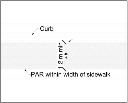
Advisory R302.3 Continuous Width. The continuous clear width requirements in R302.3 apply to sidewalks and other pedestrian circulation paths, pedestrian street crossings and at-grade rail crossings, and pedestrian overpasses and underpasses and similar structures (see R302.2). Clear width requirements are contained in R304.5.1 for curb ramps and blended transitions, and in R407.4 for ramps. Where sidewalks are wider than 1.2 m (4.0 ft), only a portion of the sidewalk is required to comply with the requirements in R302.3 through R302.7. Additional maneuvering space should be provided at turns or changes in direction, transit stops, recesses and alcoves, building entrances, and along curved or angled routes, particularly where the grade exceeds 5 percent. R210 prohibits street furniture and other objects from reducing the minimum clear width of pedestrian access routes. |
R302.3.1 Medians and Pedestrian Refuge Islands. The clear width of pedestrian access routes within medians and pedestrian refuge islands shall be 1.5 m (5.0 ft) minimum.
R302.3.2 Shared Use Paths. A pedestrian access route shall be provided for the full width of a shared use path. |
R302.4 Passing Spaces. Where the clear width of pedestrian access routes is less than 1.5 m (5.0 ft), passing spaces shall be provided at intervals of 61 m (200.0 ft) maximum. Passing spaces shall be 1.5 m (5.0 ft) minimum by 1.5 m (5.0 ft) minimum. Passing spaces are permitted to overlap pedestrian access routes.
Figure R302.4 Passing Spaces
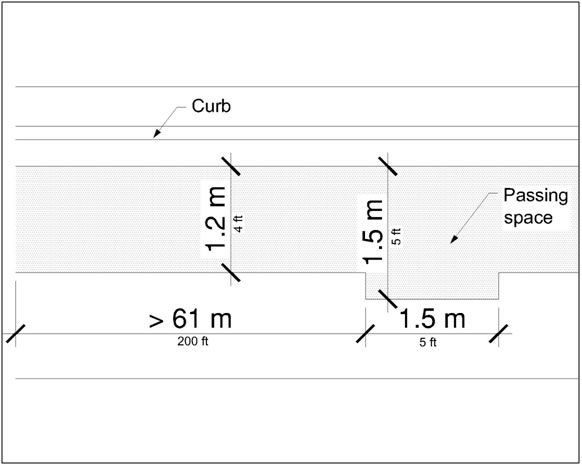
R302.5 Grade. The grade of pedestrian access routes shall comply with R302.5. |
Advisory R302.5 Grade. The grade requirements in R302.5 apply to sidewalks and other pedestrian circulation paths, pedestrian street crossings and at-grade rail crossings, and pedestrian overpasses and underpasses and similar structures (see R302.2). The grade of the pedestrian access route is measured parallel to the direction of pedestrian travel. Running slope requirements are contained in R304.2.2 for perpendicular curb ramps, in R304.3.2 for parallel curb ramps, in R304.4.1 for blended transitions, and in R407.2 for ramps. |
R302.6 Cross Slope. Except as provided in R302.6.1 and R302.6.2, the cross slope of pedestrian access routes shall be 2 percent maximum.
Advisory R302.6 Cross Slope. The cross slope requirements in R302.6 apply to sidewalks and other pedestrian circulation paths, pedestrian street crossings and at-grade rail crossings, and pedestrian overpasses and underpasses and similar structures (see R302.2). The cross slope of the pedestrian access route is measured perpendicular to the direction of pedestrian travel. Cross slope requirements are contained in R304.5.3 for curb ramps and blended transitions, and in R407.3 for ramps. |
R302.6.1 Pedestrian Street Crossings Without Yield or Stop Control. Where pedestrian access routes are contained within pedestrian street crossings without yield or stop control, the cross slope of the pedestrian access route shall be 5 percent maximum.
Advisory R302.6.1 Pedestrian Street Crossings Without Yield or Stop Control. Pedestrian street crossings without yield or stop control are crossings where there is no yield or stop sign, or where there is a traffic signal that is designed for the green phase. At pedestrian street crossings without yield or stop control, vehicles can proceed through the intersection without slowing or stopping. Where pedestrian access routes are contained within pedestrian street crossings with yield or stop control, the cross slope of the pedestrian access route must be 2 percent maximum (see R302.6). At pedestrian street crossings with yield or stop control, vehicles slow or stop before proceeding through the intersection. |
R302.6.2 Midblock Pedestrian Street Crossings. Where pedestrian access routes are contained within midblock pedestrian street crossings, the cross slope of the pedestrian access route shall be permitted to equal the street or highway grade.
R302.7 Surfaces. The surfaces of pedestrian access routes and elements and spaces required to comply with R302.7 that connect to pedestrian access routes shall be firm, stable, and slip resistant and shall comply with R302.7.
Advisory R302.7 Surfaces. The surface requirements in R302.7 apply to sidewalks and other pedestrian circulation paths, pedestrian street crossings and at-grade rail crossings, pedestrian overpasses and underpasses and similar structures, and curb ramps and blended transitions (see R302.2). The surface requirements in R302.7 also apply to surfaces at the following accessible elements and spaces that connect to pedestrian access routes:
|
R302.7.1 Vertical Alignment. Vertical alignment shall be generally planar within pedestrian access routes (including curb ramp runs, blended transitions, turning spaces, and gutter areas within pedestrian access routes) and surfaces at other elements and spaces required to comply with R302.7 that connect to pedestrian access routes. Grade breaks shall be flush. Where pedestrian access routes cross rails at grade, the pedestrian access route surface shall be level and flush with the top of rail at the outer edges of the rails, and the surface between the rails shall be aligned with the top of rail.
Advisory R302.7.1 Vertical Alignment. Pedestrian access route surfaces must be generally planar and smooth. Surfaces should be chosen for easy rollability. Surfaces that are heavily textured, rough, or chamfered and paving systems consisting of individual units that cannot be laid in plane will greatly increase rolling resistance and subject pedestrians who use wheelchairs, scooters, and rolling walkers to the stressful and often painful effects of vibration. Such materials should be reserved for borders and decorative accents located outside of or only occasionally crossing the pedestrian access route. Surfaces should be designed, constructed, and maintained according to appropriate industry standards, specifications, and recommendations for best practice. |
R302.7.2 Vertical Surface Discontinuities. Vertical surface discontinuities shall be 13 mm (0.5 in) maximum. Vertical surface discontinuities between 6.4 mm (0.25 in) and 13 mm (0.5 in) shall be beveled with a slope not steeper than 50 percent. The bevel shall be applied across the entire vertical surface discontinuity.
Figure R302.7.2 Vertical Surface Discontinuities
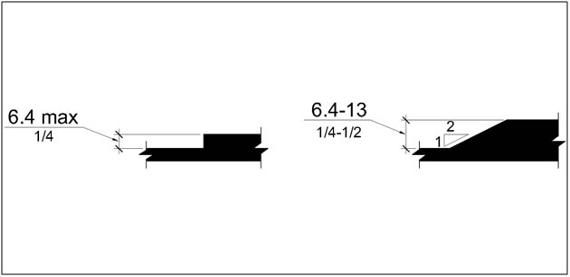
Advisory R302.7.2 Vertical Surface Discontinuities. The allowance for vertical surface discontinuities is for occasional expansion joints and objects such as utility covers, vault frames, and gratings that cannot be located in another portion of the sidewalk outside the pedestrian access route. However, objects such as utility covers, vault frames, and gratings should not be located on curb ramp runs, blended transitions, turning spaces, or gutter areas within the pedestrian access route. This may not always be possible in alterations, but should be avoided wherever possible. Vertical surface discontinuities between unit pavers should be minimized. |
R302.7.3 Horizontal Openings. Horizontal openings in gratings and joints shall not permit passage of a sphere more than 13 mm (0.5 in) in diameter. Elongated openings in gratings shall be placed so that the long dimension is perpendicular to the dominant direction of travel.
Figure R302.7.3 Horizontal Openings
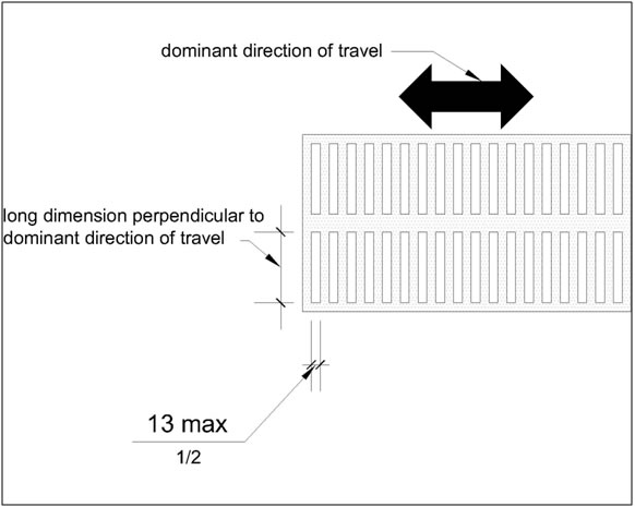
R302.7.4 Flangeway Gaps. Flangeway gaps at pedestrian at-grade rail crossings shall be 64 mm (2.5 in) maximum on non-freight rail track and 75 mm (3 in) maximum on freight rail track.
Figure R302.7.4 Flangeway Gaps

Advisory R302.7.4 Flangeway Gaps. Flangeway gaps are necessary to allow the passage of train wheel flanges. Flangeway gaps pose a potential hazard to pedestrians who use wheelchairs because the gaps can entrap the wheelchair casters. |
R303 Alternate Pedestrian Access Routes (See R205)
R304 Curb Ramps and Blended Transitions
R304.1 General. Curb ramps and blended transitions shall comply with R304.
Advisory R304.1 General. There are two types of curb ramps:
Perpendicular curb ramps can be provided where the sidewalk is at least 3.7 m (12.0 ft) wide. Parallel curb ramps can be provided where the sidewalk is at least 1.2 m (4.0 ft) wide. Parallel and perpendicular curb ramps can be combined. A parallel curb ramp is used to lower the sidewalk to a mid-landing and a short perpendicular curb ramp connects the landing to the street. Combination curb ramps can be provided where the sidewalk is at least 1.8 m (6.0 ft) wide. Blended transitions are raised pedestrian street crossings, depressed corners, or similar connections between pedestrian access routes at the level of the sidewalk and the level of the pedestrian street crossing that have a grade of 5 percent or less. Blended transitions are suitable for a range of sidewalk conditions. |
R304.2 Perpendicular Curb Ramps. Perpendicular curb ramps shall comply with R304.2 and R304.5.
R304.2.1 Turning Space. A turning space 1.2 m (4.0 ft) minimum by 1.2 m (4.0 ft) minimum shall be provided at the top of the curb ramp and shall be permitted to overlap other turning spaces and clear spaces. Where the turning space is constrained at the back-of-sidewalk, the turning space shall be 1.2 m (4.0 ft) minimum by 1.5 m (5.0 ft) minimum. The 1.5 m (5.0 ft) dimension shall be provided in the direction of the ramp run.
Figure R304.2.1 Turning Space
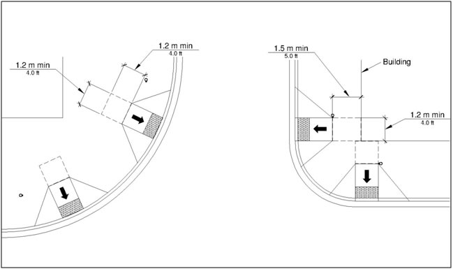
R304.2.2 Running Slope. The running slope of the curb ramp shall cut through or shall be built up to the curb at right angles or shall meet the gutter grade break at right angles where the curb is curved. The running slope of the curb ramp shall be 5 percent minimum and 8.3 percent maximum but shall not require the ramp length to exceed 4.5 m (15.0 ft). The running slope of the turning space shall be 2 percent maximum.
R304.2.3 Flared Sides. Where a pedestrian circulation path crosses the curb ramp, flared sides shall be sloped 10 percent maximum, measured parallel to the curb line.
Figure 304.2.3 Flared Sides
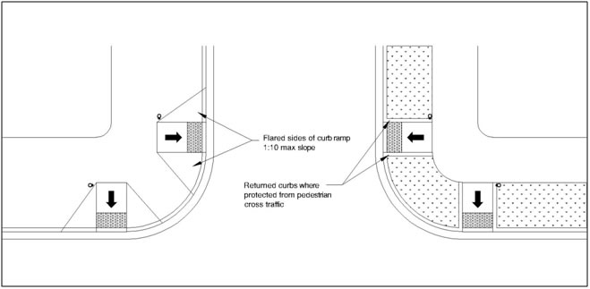
Advisory R304.2.3 Flared Sides. The flared sides are part of the pedestrian circulation path, but are not part of the pedestrian access route. Curb ramps whose sides have returned curbs provide useful directional cues where they are aligned with the pedestrian street crossing and are protected from cross travel by landscaping, street furniture, chains, fencing, or railings. |
R304.3 Parallel Curb Ramps. Parallel curb ramps shall comply with R304.3 and R304.5.
R304.3.1 Turning Space. A turning space 1.2 m (4.0 ft) minimum by 1.2 m (4.0 ft) minimum shall be provided at the bottom of the curb ramp and shall be permitted to overlap other turning spaces and clear spaces. If the turning space is constrained on 2 or more sides, the turning space shall be 1.2 m (4.0 ft) minimum by 1.5 m (5.0 ft). The 1.5 m (5.0 ft) dimension shall be provided in the direction of the pedestrian street crossing.
Figure R304.3.1 Turning Space
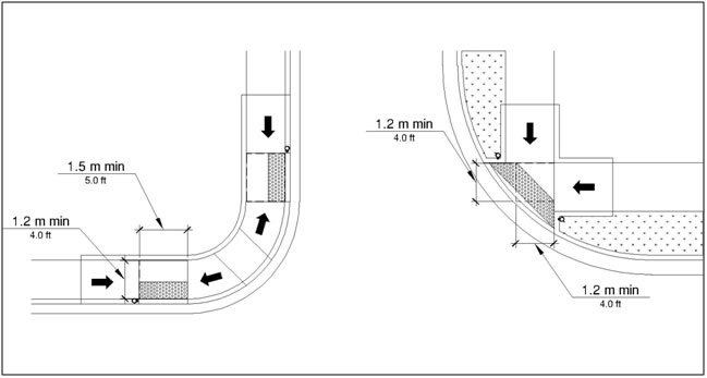
R304.3.2 Running Slope. The running slope of the curb ramp shall be in-line with the direction of sidewalk travel. The running slope of the curb ramp shall be 5 percent minimum and 8.3 percent maximum but shall not require the ramp length to exceed 4.5 m (15.0 ft) minimum. The running slope of the turning space shall be 2 percent maximum.
R304.4 Blended Transitions. Blended transitions shall comply with R304.4 and R304.5.
R304.4.1 Running Slope. The running slope of blended transitions shall be 5 percent maximum.
Figure R304.4.1 Running Slope

R304.5 Common Requirements. Curb ramps and blended transitions shall comply with R304.5.
Figure R304.5.1 Width
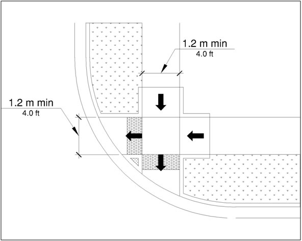
R304.5.2 Grade Breaks. Grade breaks at the top and bottom of curb ramp runs shall be perpendicular to the direction of the ramp run. Grade breaks shall not be permitted on the surface of ramp runs and turning spaces. Surface slopes that meet at grade breaks shall be flush.
Figure R304.5.2 Grade Breaks
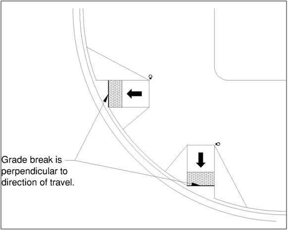
R304.5.3 Cross Slope. The cross slope of curb ramps, blended transitions, and turning spaces shall be 2 percent maximum. At pedestrian street crossings without yield or stop control and at midblock pedestrian street crossings, the cross slope shall be permitted to equal the street or highway grade.
Advisory R304.5.3 Cross Slope. Pedestrian street crossings without yield or stop control are crossings where there is no yield or stop sign, or where there is a traffic signal that is designed for the green phase. At pedestrian street crossings without yield or stop control, vehicles can proceed through the intersection without slowing or stopping. |
R304.5.4 Counter Slope. The counter slope of the gutter or street at the foot of curb ramp runs, blended transitions, and turning spaces shall be 5 percent maximum.
R304.5.5 Clear Space. Beyond the bottom grade break, a clear space 1.2 m (4.0 ft) minimum by 1.2 m (4.0 ft) minimum shall be provided within the width of the pedestrian street crossing and wholly outside the parallel vehicle travel lane.
Figure R304.5.5 Clear Space
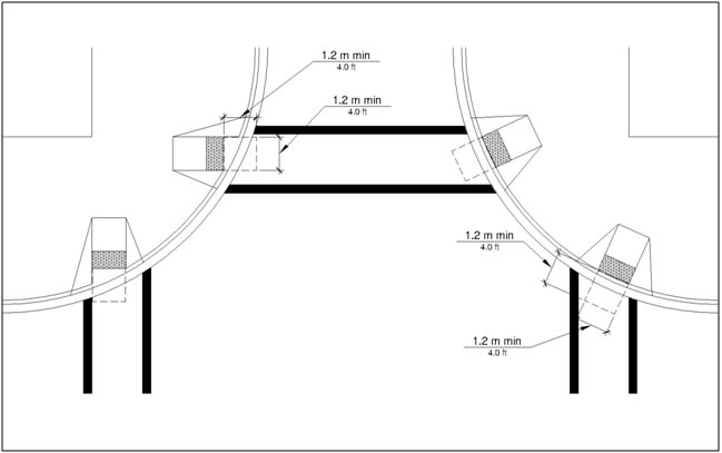
R305 Detectable Warning Surfaces
R305.1 General. Detectable warning surfaces shall consist of truncated domes aligned in a square or radial grid pattern and shall comply with R305.
Advisory R305.1 Dome Size. Where the truncated domes are arrayed radially, they may differ in diameter and center-to-center spacing within the ranges specified in R305.1.1 and R305.1.2. |
R305.1.1 Dome Size. The truncated domes shall have a base diameter of 23 mm (0.9 in) minimum and 36 mm (1.4 in) maximum, a top diameter of 50 percent of the base diameter minimum and 65 percent of the base diameter maximum, and a height of 5 mm (0.2 in).
Figure R305.1.1 Dome Size
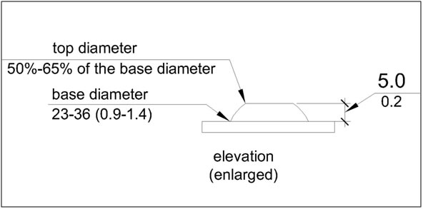
R305.1.2 Dome Spacing. The truncated domes shall have a center-to-center spacing of 41 mm (1.6 in) minimum and 61 mm (2.4 in) maximum, and a base-to-base spacing of 17 mm (0.65 in) minimum, measured between the most adjacent domes.
Figure R305.1.2 Dome Spacing
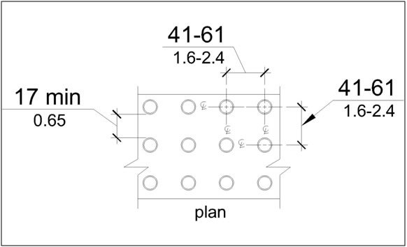
R305.1.3 Contrast. Detectable warning surfaces shall contrast visually with adjacent gutter, street or highway, or pedestrian access route surface, either light-on-dark or dark-on-light.
Advisory R305.1.3 Contrast. Visual contrast may be provided on the full surface of the curb ramp but should not extend to flared sides. Visual contrast also helps pedestrians who use wheelchairs to locate the curb ramp from the other side of the street. |
R305.1.4 Size. Detectable warning surfaces shall extend 610 mm (2.0 ft) minimum in the direction of pedestrian travel. At curb ramps and blended transitions, detectable warning surfaces shall extend the full width of the ramp run (excluding any flared sides), blended transition, or turning space. At pedestrian at-grade rail crossings not located within a street or highway, detectable warnings shall extend the full width of the crossing. At boarding platforms for buses and rail vehicles, detectable warning surfaces shall extend the full length of the public use areas of the platform. At boarding and alighting areas at sidewalk or street level transit stops for rail vehicles, detectable warning surfaces shall extend the full length of the transit stop.
Figure R305.1.4 Size
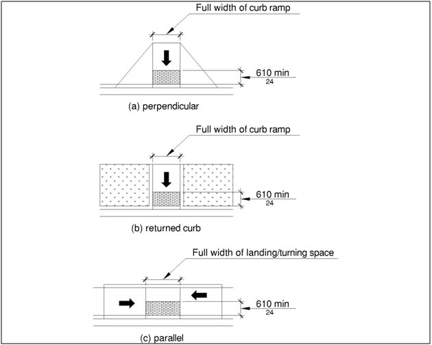
R305.2 Placement. The placement of detectable warning surfaces shall comply with R305.2.
Advisory R305.2 Placement. Some detectable warning products require a concrete border for proper installation. The concrete border should not exceed 51 mm (2 in). Where the back of curb edge is tooled to provide a radius, the border dimension should be measured from the end of the radius. |
R305.2.1 Perpendicular Curb Ramps. On perpendicular curb ramps, detectable warning surfaces shall be placed as follows:
Figure R305.2.1 Perpendicular Curb Ramps
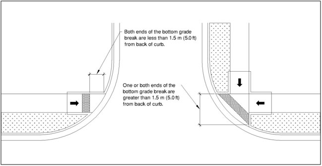
Advisory R305.2.1 Perpendicular Curb Ramps. Detectable warning surfaces are intended to provide a tactile equivalent underfoot of the visible curb line. If detectable warning surfaces are placed too far from the curb line because of a large curb radius, the location may compromise effective crossing. Detectable warning surfaces should not be placed on paving or expansion joints. The rows of truncated domes in detectable warning surfaces should be aligned perpendicular to the grade break between the ramp run and the street so pedestrians who use wheelchairs can "track" between the domes. Where detectable warning surfaces are provided on a surface with a slope that is less than 5 percent, dome orientation is less critical. |
R305.2.2 Parallel Curb Ramps. On parallel curb ramps, detectable warning surfaces shall be placed on the turning space at the flush transition between the street and sidewalk.
Figure R305.2.2 Parallel Curb Ramps
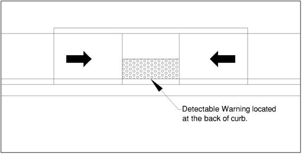
R305.2.3 Blended Transitions. On blended transitions, detectable warning surfaces shall be placed at the back of curb. Where raised pedestrian street crossings, depressed corners, or other level pedestrian street crossings are provided, detectable warning surfaces shall be placed at the flush transition between the street and the sidewalk.
Figure R305.2.3 Blended Transitions
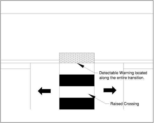
R305.2.4 Pedestrian Refuge Islands. At cut-through pedestrian refuge islands, detectable warning surfaces shall be placed at the edges of the pedestrian island and shall be separated by a 610 mm (2.0 ft) minimum length of surface without detectable warnings.
Figure R 305.2.4 Pedestrian Refuge Island
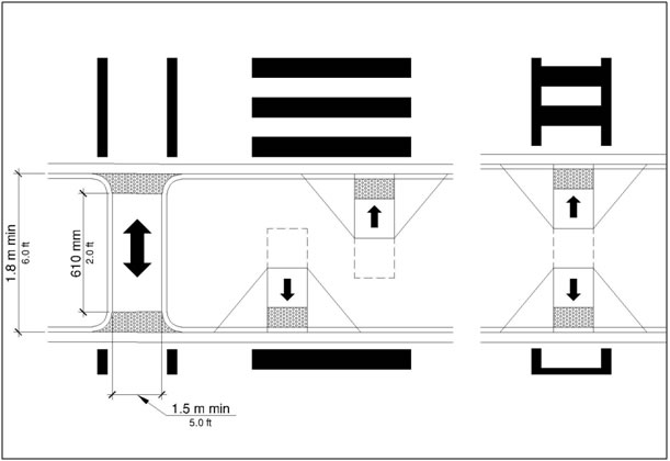
Advisory R305.2.4 Pedestrian Refuge Islands. The edges of cut-through pedestrian refuge islands can provide useful cues to the direction of the crossing. |
R305.2.5 Pedestrian At-Grade Rail Crossings. At pedestrian at-grade rail crossings not located within a street or highway, detectable warning surfaces shall be placed on each side of the rail crossing. The edge of the detectable warning surface nearest the rail crossing shall be 1.8 m (6.0 ft) minimum and 4.6 m (15.0 ft) maximum from the centerline of the nearest rail. Where pedestrian gates are provided, detectable warning surfaces shall be placed on the side of the gates opposite the rail.
Figure R305.2.5 Pedestrian At-Grade Rail Crossings
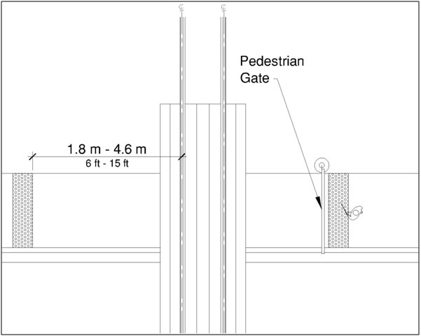
R305.2.6 Boarding Platforms. At boarding platforms for buses and rail vehicles, detectable warning surfaces shall be placed at the boarding edge of the platform.
R305.2.7 Boarding and Alighting Areas. At boarding and alighting areas at sidewalk or street level transit stops for rail vehicles, detectable warning surfaces shall be placed at the side of the boarding and alighting area facing the rail vehicles.
R306 Pedestrian Street Crossings
R306.1 General. Pedestrian street crossings shall comply with R306.
R306.2 Pedestrian Signal Phase Timing. All pedestrian signal phase timing shall comply with section 4E.06 of the MUTCD (incorporated by reference, see R104.2 and shall be based on a pedestrian clearance time that is calculated using a pedestrian walking speed of 1.1 m/s (3.5 ft/s) or less.
R306.3 Roundabouts. Where pedestrian facilities are provided at roundabouts, they shall comply with R306.3.
Advisory R306.3 Roundabouts. Pedestrian street crossings at roundabouts can be difficult for pedestrians who are blind or have low vision to identify because the crossings are located off to the side of the pedestrian circulation path around the street or highway. The continuous traffic flow at roundabouts removes many of the audible cues that pedestrians who are blind use to navigate pedestrian street crossings. Water fountains and other features that produce background noise should not be placed in the middle island of a roundabout because pedestrians who are blind use auditory cues to help detect gaps in traffic. Multi-lane pedestrian street crossings at roundabouts involve an increased risk of pedestrian exposure to accident. |
R306.3.1 Separation. Where sidewalks are flush against the curb and pedestrian street crossing is not intended, a continuous and detectable edge treatment shall be provided along the street side of the sidewalk. Detectable warning surfaces shall not be used for edge treatment. Where chains, fencing, or railings are used for edge treatment, they shall have a bottom edge 380 mm (15 in) maximum above the sidewalk.
Advisory R306.3.1 Separation. Carefully delineated pedestrian street crossing approaches with plantings or other defined edges provide effective non-visual cues for identifying pedestrian street crossings at roundabouts. European and Australian roundabouts provide a 610 mm (24 inch) width of tactile surface treatment from the centerline of the curb ramp or blended transition across the full width of the sidewalk to provide an underfoot cue for identifying pedestrian street crossings. Detectable warning surfaces should not be used to guide pedestrians who are blind or have low vision to pedestrian street crossings because detectable warning surfaces indicate the flush transition between the sidewalk and the street or highway. Schemes that remove cyclists from the street or highway by means of a ramp that angles from the curb lane to the sidewalk and then provide re-entry by means of a similar ramp beyond pedestrian street crossings can provide false cues to pedestrians who are using the edge of the sidewalk for wayfinding about the location of pedestrian street crossings. |
R306.3.2 Pedestrian Activated Signals. At roundabouts with multi-lane pedestrian street crossings, a pedestrian activated signal complying with R209 shall be provided for each multi-lane segment of each pedestrian street crossing, including the splitter island. Signals shall clearly identify which pedestrian street crossing segment the signal serves.
Advisory R306.3.2 Pedestrian Activated Signals. Roundabouts with single-lane approach and exit legs are not required to provide pedestrian activated signals. Pedestrian activated signals must comply with the requirements for accessible pedestrian signals and pedestrian pushbuttons (see R209). Pedestrian activated signals installed at splitter islands should be carefully located and separated so that signal spillover does not give conflicting information about which pedestrian street crossing has the WALK indication displayed. Pedestrian Hybrid Beacons can be used at roundabouts (see MUTCD sections 4F.01 through 4F.03). Pedestrian Hybrid Beacons are traffic signals that consist of a yellow signal centered below two horizontally aligned red signals. The signals are normally not illuminated. The signals are initiated only upon pedestrian activation and can be timed to minimize the interruption of traffic. The signals cease operation after the pedestrian clears the crosswalk. When activated by a pedestrian, the following signals are displayed to drivers: a flashing yellow signal, then a steady yellow signal, then two steady red signals during the pedestrian walk interval, and then alternating flashing red signals during the pedestrian clearance interval. The following signals are displayed to pedestrians: a steady upraised hand (symbolizing DON’T WALK) when the flashing or steady yellow signal is operating, then a walking person (symbolizing WALK) when the steady red signals are operating, and then a flashing upraised hand (symbolizing DON’T WALK) when the alternating flashing red signals are operating. |
R306.4 Channelized Turn Lanes at Roundabouts. At roundabouts with pedestrian street crossings, pedestrian activated signals complying with R209 shall be provided at pedestrian street crossings at multi-lane channelized turn lanes.
R306.5 Channelized Turn Lanes at Other Signalized Intersections. At signalized intersections other than roundabouts with pedestrian street crossings, pedestrian activated signals complying with R209 shall be provided at pedestrian street crossings at multi-lane channelized turn lanes.
R307 Accessible Pedestrian Signals and Pedestrian Pushbuttons (See R209)
R308 Transit Stops and Transit Shelters
R308.1 Transit Stops. Transit stops shall comply with R308.1.
Advisory R308.1 Transit Stops. Transit stops should be located so that there is a level and stable surface for boarding vehicles. Locating transit stops at signalized intersections increases the usability for pedestrian with disabilities. Where security bollards are installed at transit stops, they must not obstruct the clear space at boarding and alighting areas or reduce the required clear width at pedestrian access routes (see R210). |
R308.1.1 Boarding and Alighting Areas. Boarding and alighting areas at sidewalk or street level transit stops shall comply with R308.1.1 and R308.1.3. Where transit stops serve vehicles with more than one car, boarding and alighting areas serving each car shall comply with R308.1.1 and R308.1.3.
Advisory R308.1.1 Boarding and Alighting Areas. Where a transit shelter is provided, the boarding and alighting area can be located either within or outside of the shelter. |
R308.1.1.1 Dimensions. Boarding and alighting areas shall provide a clear length of 2.4 m (8.0 ft) minimum, measured perpendicular to the curb or street or highway edge, and a clear width of 1.5 m (5.0 ft) minimum, measured parallel to the street or highway.
Figure R308.1.1.1 Dimensions
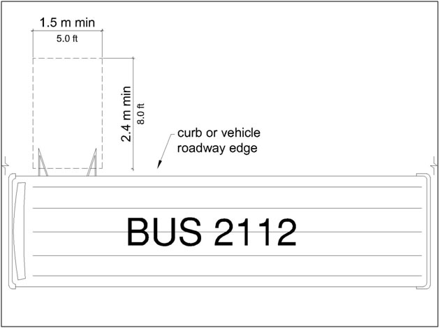
R308.1.1.2 Grade. Parallel to the street or highway, the grade of boarding and alighting areas shall be the same as the street or highway, to the extent practicable. Perpendicular to the street or highway, the grade of boarding and alighting areas shall not be steeper than 2 percent.
R308.1.2 Boarding Platforms. Boarding platforms at transit stops shall comply with R308.1.2 and R308.1.3.
R308.1.2.1 Platform and Vehicle Floor Coordination. Boarding platforms shall be positioned to coordinate with vehicles in accordance with the applicable requirements in 49 CFR parts 37 and 38.
Advisory R308.1.2.1 Platform and Vehicle Floor Coordination. The Department of Transportation regulations (49 CFR parts 37 and 38) require the height of the vehicle floor and the station platform to be coordinated so as to minimize the vertical and horizontal gaps. |
R308.1.2.2 Slope. Boarding platforms shall not exceed a slope of 2 percent in any direction. Where boarding platforms serve vehicles operating on existing track or existing street or highway, the slope of the platform parallel to the track or the street or highway is permitted to be equal to the grade of the track or street or highway.
R308.1.3 Common Requirements. Boarding and alighting areas and boarding platforms shall comply with R308.1.3.
R308.1.3.1 Surfaces. The surfaces of boarding and alighting areas and boarding platforms shall comply with R302.7.
Advisory R308.1.3.1 Surfaces. Detectable warning surfaces are required at boarding and alighting areas for rail vehicles and at boarding platforms for buses and rail vehicles (see R208). |
R308.1.3.2 Connection. Boarding and alighting areas and boarding platforms shall be connected to streets, sidewalks, or pedestrian circulation paths by pedestrian access routes complying with R302.
Figure R308.1.3.2 Connection
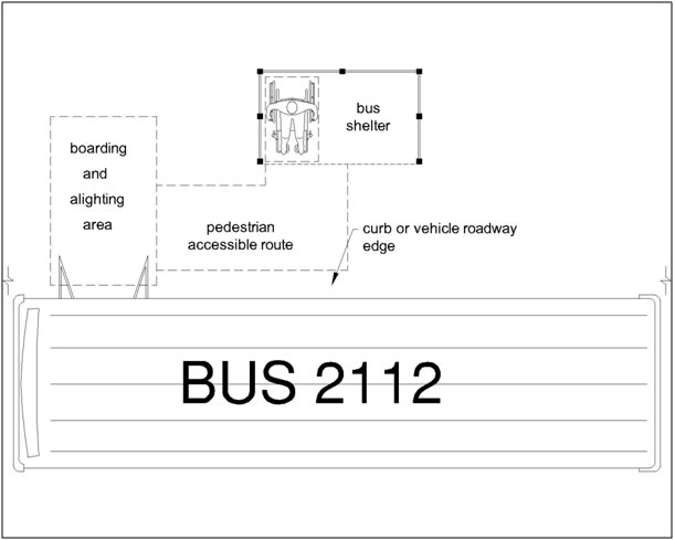
R308.2 Transit Shelters. Transit shelters shall be connected by pedestrian access routes complying with R302 to boarding and alighting areas or boarding platforms complying with R308.1. Transit shelters shall provide a minimum clear space complying with R404 entirely within the shelter. Where seating is provided within transit shelters, the clear space shall be located either at one end of a seat or shall not overlap the area within 460 mm (1.5 ft) from the front edge of the seat. Environmental controls within transit shelters shall be proximity-actuated. Protruding objects within transit shelters shall comply with R402.
Advisory R308.2 Transit Shelters. The clear space must be located entirely within the transit shelter and not interfere with other persons using the seating. |
R309 On-Street Parking Spaces
R309.1 General. On-street parking spaces shall comply with R309.
Advisory R309.1 General. R214 specifies how many accessible parking spaces must be provided on the block perimeter where on-street parking is marked or metered. Accessible parking spaces must be identified by signs displaying the International Symbol of Accessibility (see R211.3 and R411). Accessible parking spaces should be located where the street has the least crown and grade and close to key destinations. |
R309.2 Parallel Parking Spaces. Parallel parking spaces shall comply with R309.2.
Advisory R309.2 Parallel Parking Spaces. The sidewalk adjacent to accessible parallel parking spaces should be free of signs, street furniture, and other obstructions to permit deployment of a van side-lift or ramp or the vehicle occupant to transfer to a wheelchair or scooter. Accessible parallel parking spaces located at the end of the block face are usable by vans that have rear lifts and cars that have scooter platforms. |
R309.2.1 Wide Sidewalks. Where the width of the adjacent sidewalk or available right-of-way exceeds 4.3 m (14.0 ft), an access aisle 1.5 m (5.0 ft) wide minimum shall be provided at street level the full length of the parking space and shall connect to a pedestrian access route. The access aisle shall comply with R302.7 and shall not encroach on the vehicular travel lane.
Figure R309.2.1 Wide Sidewalks
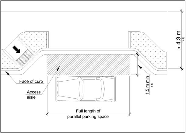
Advisory R309.2.1 Wide Sidewalks. Vehicles may park at the curb or at the parking lane boundary and use the space required by R309.2.1 on either the driver or passenger side of the vehicle to serve as the access aisle. |
R309.2.1.1 Alterations. In alterations where the street or sidewalk adjacent to the parking spaces is not altered, an access aisle shall not be required provided the parking spaces are located at the end of the block face.
R309.2.2 Narrow Sidewalks. An access aisle is not required where the width of the adjacent sidewalk or the available right-of-way is less than or equal to 4.3 m (14.0 ft). When an access aisle is not provided, the parking spaces shall be located at the end of the block face.
Figure R309.2.2 Narrow Sidewalks
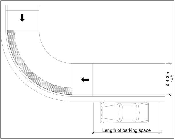
Advisory R309.2.2 Narrow Sidewalks. Vehicle lifts or ramps can be deployed on a 2.4 m (8.0 ft) sidewalk if there are no obstructions. |
R309.3 Perpendicular or Angled Parking Spaces. Where perpendicular or angled parking is provided, an access aisle 2.4 m (8.0 ft) wide minimum shall be provided at street level the full length of the parking space and shall connect to a pedestrian access route. The access aisle shall comply with R302.7 and shall be marked so as to discourage parking in the access aisle. Two parking spaces are permitted to share a common access aisle.
Figure R309.3 Perpendicular or Angled Parking Spaces
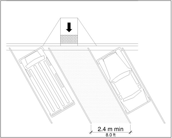
Advisory R309.3 Perpendicular or Angled Parking Spaces. Perpendicular and angled parking spaces permit the deployment of a van side-lift or ramp. |
R309.4 Curb Ramps or Blended Transitions. Curb ramps or blended transitions complying with R304 shall connect the access aisle to the pedestrian access route. Curb ramps shall not be located within the access aisle.
Advisory R309.4 Curb Ramps or Blended Transitions. At parallel parking spaces, curb ramps and blended transitions should be located so that a van side-lift or ramp can be deployed to the sidewalk and the vehicle occupant can transfer to a wheelchair or scooter. Parking spaces at the end of the block face can be served by curb ramps or blended transitions at the pedestrian street crossing. Detectable warning surfaces are not required on curb ramps and blended transitions that connect the access aisle to the sidewalk, including where the sidewalk is at the same level as the parking spaces, unless the curb ramps and blended transitions also serve pedestrian street crossings (see R208). |
R309.5 Parking Meters and Parking Pay Stations. Parking meters and parking pay stations that serve accessible parking spaces shall comply with R309.5. Operable parts shall comply with R403.
R309.5.1 Location. At accessible parallel parking spaces, parking meters shall be located at the head or foot of the parking space.
Advisory R309.5.1 Location. Locating parking meters at the head or foot of the parking space permits deployment of a van side-lift or ramp or the vehicle occupant to transfer to a wheelchair or scooter. |
R309.5.2 Displays and Information. Displays and information shall be visible from a point located 1.0 m (3.3 ft) maximum above the center of the clear space in front of the parking meter or parking pay station.
R310 Passenger Loading Zones
R310.1 General. Passenger loading zones shall comply with R310.
Advisory R310.1 General. Accessible passenger loading zones must be identified by signs displaying the International Symbol of Accessibility (see R211.3 and R411). |
R310.2 Vehicle Pull-Up Space. Passenger loading zones shall provide a vehicular pull-up space 2.4 m (8.0 ft) wide minimum and 6.1 m (20.0 ft) long minimum.
R310.3 Access Aisle. Passenger loading zones shall provide access aisles complying with R310.3 adjacent to the vehicle pull-up space. Access aisles shall be at the same level as the vehicle pull-up space they serve and shall not overlap the vehicular travel lane. Curb ramps or blended transitions complying with R304 shall connect the access aisle to the pedestrian access route. Curb ramps are not permitted within the access aisle.
Figure R310.3 Access Aisle
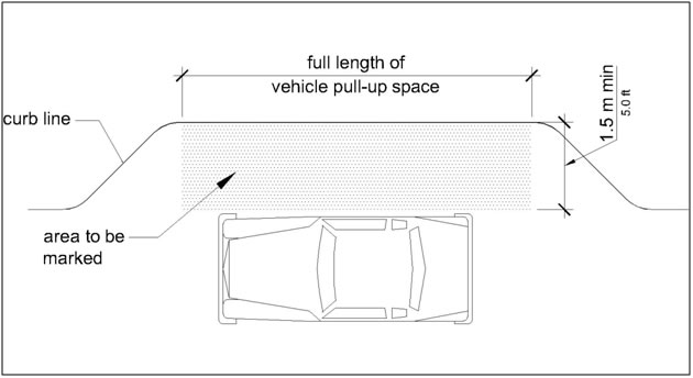
R310.3.1 Width. Access aisles serving vehicle pull-up spaces shall be 1.5 m (5.0 ft) wide minimum.
R310.3.2 Length. Access aisles shall extend the full length of the vehicle pull-up spaces they serve.
R310.3.3 Marking. Access aisles shall be marked so as to discourage parking in them.
R310.3.4 Surfaces. Access aisle surfaces shall comply with R302.7.
CHAPTER R4: SUPPLEMENTARY TECHNICAL REQUIREMENTS
R401 General
R401.1 Scope. The supplemental technical requirements in Chapter 4 shall apply where required by Chapter 2 or where referenced by a requirement in this document.
R402 Protruding Objects
R402.1 General. Protruding objects shall comply with R402.
R402.2 Protrusion Limits. Objects with leading edges more than 685 mm (2.25 ft) and not more than 2 m (6.7 ft) above the finish surface shall protrude 100 mm (4 in) maximum horizontally into pedestrian circulation paths.
Figure R402.2 Protrusion Limits
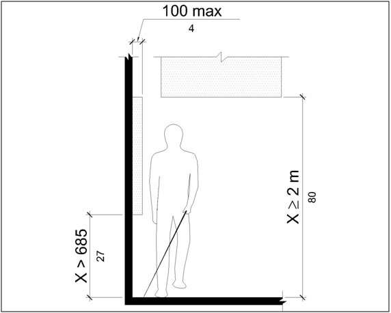
R402.3 Post-Mounted Objects. Where objects are mounted on free-standing posts or pylons and the objects are 685 mm (2.25 ft) minimum and 2030 mm (6.7 ft) maximum above the finish surface, the objects shall overhang pedestrian circulation paths 100 mm (4 in) maximum measured horizontally from the post or pylon base. The base dimension shall be 64 mm (2.5 in) thick minimum. Where objects are mounted between posts or pylons and the clear distance between the posts or pylons is greater than 305 mm (1.0 ft), the lowest edge of the object shall be 685 mm (2.25 ft) maximum or 2 m (6.7 ft) minimum above the finish surface.
Figure R402.3 Post-Mounted Objects
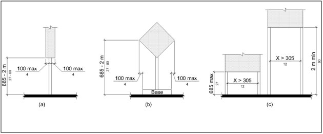
R402.4 Reduced Vertical Clearance. Guardrails or other barriers to pedestrian travel shall be provided where the vertical clearance is less than 2 m (6.7 ft) high. The leading edge of the guardrail or barrier shall be located 685 mm (2.25 ft) maximum above the finish surface.
Figure R402.4 Reduced Vertical Clearance
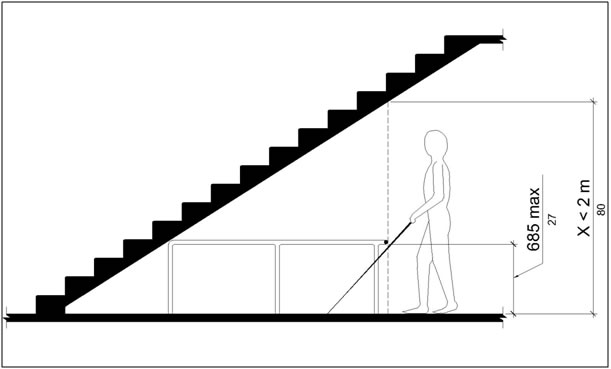
R403 Operable Parts
R403.1 General. Operable parts shall comply with R403.
Advisory R403.1 General. Operable parts on accessible pedestrian signals and pedestrian pushbuttons (see R209) and parking meters and parking pay stations that serve accessible parking spaces (see R309.5) must comply with R403. |
R403.2 Clear Space. A clear space complying with R404 shall be provided at operable parts.
R403.3 Height. Operable parts shall be placed within one or more of the reach ranges specified in R406.
R403.4 Operation. Operable parts shall be operable with one hand and shall not require tight grasping, pinching, or twisting of the wrist. The force required to activate operable parts shall be 22 N (5 lbs) maximum.
R404 Clear Spaces
R404.1 General. Clear spaces shall comply with R404.
Advisory R404.1 General. Clear spaces are required at operable parts (see R403.2), including accessible pedestrian signals and pedestrian pushbuttons (see R209) and parking meters and parking pay stations that serve accessible parking spaces (see R309.5). Clear spaces are also required at benches (see R212.6) and within transit shelters (see R308.2). |
R404.2 Surfaces. Surfaces of clear spaces shall comply with R302.7 and shall have a running slope consistent with the grade of the adjacent pedestrian access route and cross slope of 2 percent maximum.
R404.3 Size. Clear spaces shall be 760 mm (2.5 ft) minimum by 1220 mm (4.0 ft) minimum.
R404.4 Knee and Toe Clearance. Unless otherwise specified, clear spaces shall be permitted to include knee and toe clearance complying with R405.
R404.5.Position. Unless otherwise specified, clear spaces shall be positioned for either forward or parallel approach to an element.
R404.6 Approach. One full unobstructed side of a clear space shall adjoin a pedestrian access route or adjoin another clear space.
R404.7 Maneuvering Space. Where a clear space is confined on all or part of three sides, additional maneuvering space shall be provided in accordance with R404.7.1 and R404.7.2.
R404.7.1 Forward Approach. The clear space and additional maneuvering space shall be 915 mm (3.0 ft) wide minimum where the depth exceeds 610 mm (2.0 ft).
R404.7.2 Parallel Approach. The clear space and additional maneuvering space shall be 1525 mm (5.0 ft) wide minimum where the depth exceeds 380 mm (1.25 ft).
R405 Knee and Toe Clearance
R405.1 General. Where space beneath an element is included as part of a clear space, the space shall comply with R405. Additional space shall not be prohibited beneath an element but shall not be considered as part of the clear space.
Advisory R405.1 General. Clearances are measured in relation to the usable clear space, not necessarily to the vertical support for an element. When determining clearance under an object, care should be taken to ensure that the space is clear of any obstructions. |
R405.2 Toe Clearance
R405.2.1 General. Space under an element between the finish surface and 230 mm (9 in) above the finish surface shall be considered toe clearance and shall comply with R405.2.
R405.2.2 Maximum Depth. Toe clearance shall extend 635 mm (2.1 ft) maximum under an element.
R405.2.3 Minimum Required Depth. Where toe clearance is required at an element as part of a clear space, the toe clearance shall extend 430 mm (1.4 ft) minimum under the element.
R405.2.4 Width. Toe clearance shall be 760 mm (2.5 ft) wide minimum.
Figure R405.2 Toe Clearance
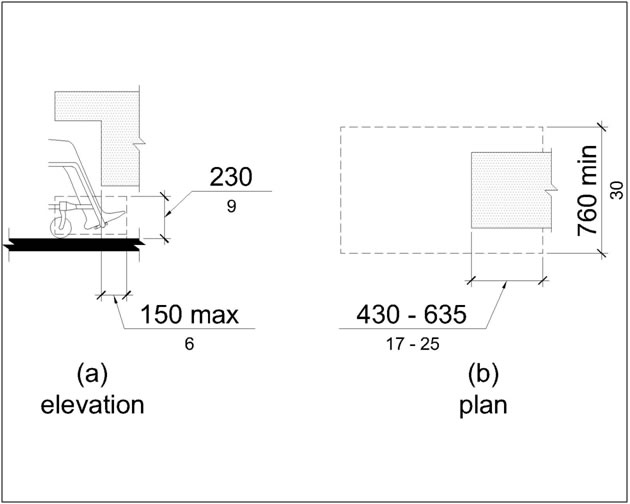
R405.3 Knee Clearance
R405.3.1 General. Space under an element between 230 mm (9 in) and 685 mm (2.25 ft) above the finish surface shall be considered knee clearance and shall comply with R405.3.
R405.3.2 Maximum Depth. Knee clearance shall extend 635 mm (2.1 ft) maximum under an element at 230 mm (9 in) above the finish surface.
R405.3.3 Minimum Required Depth. Where knee clearance is required under an element as part of a clear space, the knee clearance shall be 280 mm (11 in) deep minimum at 230 mm (9 in) above the finish surface, and 205 mm (8 in) deep minimum at 685 mm (2.25 ft) above the finish surface.
R405.3.4 Clearance Reduction. Between 230 mm (9 in) and 685 mm (2.25 ft) above the finish surface, the knee clearance shall be permitted to reduce at a rate of 25 mm (1 in) in depth for each 150 mm (6 in) in height.
R405.3.5 Width. Knee clearance shall be 760 mm (2.5 ft) wide minimum.
Figure R405.3 Knee Clearance
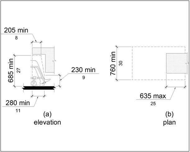
R406 Reach Ranges
R406.1 General. Reach ranges shall comply with R406.
R406.2 Unobstructed Forward Reach. Where a forward reach is unobstructed, the high forward reach shall be 1220 mm (4.0 ft) maximum and the low forward reach shall be 380 mm (1.25 ft) minimum above the finish surface. Forward reach over an obstruction is not permitted.
Figure R406.2 Unobstructed Forward Reach
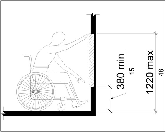
R406.3 Unobstructed Side Reach. Where a clear space allows a parallel approach to an element and the side reach is unobstructed, the high side reach shall be 1220 mm (4.0 ft) maximum and the low side reach shall be 380 mm (1.25 ft) minimum above the finish surface. An obstruction shall be permitted between the clear space and the element where the depth of the obstruction is 255 mm (10 in) maximum.
Figure R406.3 Unobstructed Side Reach
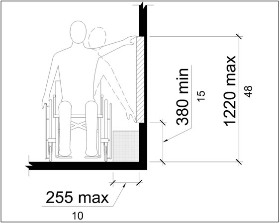
R407 Ramps
R407.1 General. Ramps shall comply with R407.
R407.2 Running Slope. Ramp runs shall have a running slope between 5 percent minimum and 8.3 percent maximum.
Advisory R407.2 Running Slope. Ramps with the least possible running slope accommodate the widest range of users. Providing stairways along with ramps, where possible, benefits pedestrians with heart disease, limited stamina, and others for whom distance presents a greater barrier than steps. |
R407.3 Cross Slope. The cross slope of ramp runs shall be 2 percent maximum.
R407.4 Width. The clear width of a ramp run and, where handrails are provided, the clear width between handrails shall be 915 mm (3.0 ft) minimum.
R407.5 Rise. The rise for any ramp run shall be 760 mm (2.5 ft) maximum.
R407.6 Landings. Ramps shall have landings at the top and the bottom of each ramp run. Landings shall comply with R407.6.
Figure R407.6 Landings
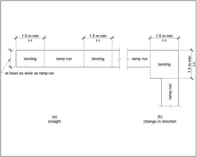
R407.6.1 Slope. Landing slopes shall be 2 percent maximum in any direction.
R407.6.2 Width. The landing clear width shall be at least as wide as the widest ramp run leading to the landing.
R407.6.3 Length. The landing clear length shall be 1.5 m (5.0 ft) long minimum.
R407.6.4 Change in Direction. Ramps that change direction between runs at landings shall have a clear landing 1.5 m (5.0 ft) minimum by 1.5 m (5.0 ft) minimum.
R407.7 Surfaces. Surfaces of ramp runs and landings shall comply with R302.7.
R407.8 Handrails. Ramp runs with a rise greater than 150 mm (6 in) shall have handrails complying with R409.
R407.9 Edge Protection. Edge protection complying with R407.9.1 or R407.9.2 shall be provided on each side of ramp runs and ramp landings.
R407.9.1 Extended Ramp Surface. The surface of the ramp run or landing shall extend 305 mm (1.0 ft) minimum beyond the inside face of a handrail complying with R409.
Figure R407.9.1 Extended Ramp Surface
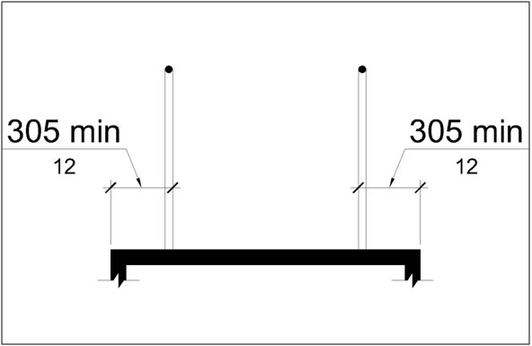
Advisory R407.9.1 Extended Ramp Surface. The extended surface prevents wheelchair casters and crutch tips from slipping off the ramp surface. |
R407.9.2 Curb or Barrier. A curb or barrier shall be provided that prevents the passage of a 100 mm (4 in) diameter sphere, where any portion of the sphere is within 100 mm (4 in) of the finish surface.
R408 Stairways
R408.1 General. Stairways shall comply with R408.
R408.2 Treads and Risers. All steps on a flight of stairs shall have uniform riser heights and uniform tread depths. Risers shall be 100 mm (4 in) high minimum and 180 mm (7 in) high maximum. Treads shall be 280 mm (11 in) deep minimum.
R408.3 Open Risers. Open risers are not permitted.
R408.4 Tread Surface. Stairway treads shall comply with R302.7. Changes in level are not permitted.
R408.5 Nosings. The radius of curvature at the leading edge of the tread shall be 13 mm (0.5 inch) maximum. Nosings that project beyond risers shall have the underside of the leading edge curved or beveled. Risers shall be permitted to slope under the tread at an angle of 30 degrees maximum from vertical. The permitted projection of the nosing shall extend 38 mm (1.5 in) maximum over the tread below.
R408.6 Handrails. Stairways shall have handrails complying with R409.
R409 Handrails
R409.1 General. Handrails required at ramps and stairways, and handrails provided on pedestrian circulation paths shall comply with R409.
Advisory R409.1 General. Handrails are required on ramp runs with a rise greater than 150 mm (6 in) (see R407.8) and stairways (see R408.6). Handrails are not required on pedestrian circulation paths. However, if handrails are provided on pedestrian circulation paths, the handrails must comply with R409 (see R217). The requirements in R409.2, R409.3, and R409.10 apply only to handrails at ramps and stairways, and do not apply to handrails provided on pedestrian circulation paths. |
R409.2 Where Required. Handrails shall be provided on both sides of ramps and stairways.
R409.3 Continuity. Handrails shall be continuous within the full length of each ramp run or stair flight. Inside handrails on switchback or dogleg ramps and stairways shall be continuous between ramp runs or stair flights.
R409.4 Height. Top of gripping surfaces of handrails shall be 865 mm (2.8 ft) minimum and 965 mm (3.2 ft) maximum vertically above walking surfaces, ramp surfaces, and stair nosings. Handrails shall be at a consistent height above walking surfaces, ramp surfaces, and stair nosings.
Figure R409.4 Height
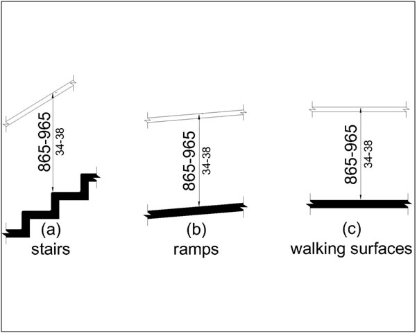
R409.5 Clearance. Clearance between handrail gripping surfaces and adjacent surfaces shall be 38 mm (1.5 in) minimum.
R409.6 Gripping Surface. Handrail gripping surfaces shall be continuous along their length and shall not be obstructed along their tops or sides. The bottoms of handrail gripping surfaces shall not be obstructed for more than 20 percent of their length. Where provided, horizontal projections shall occur 38 mm (1.5 in) minimum below the bottom of the handrail gripping surface.
Advisory R409.6 Gripping Surface. Pedestrians with disabilities and others benefit from continuous gripping surfaces that permit users to reach the fingers outward or downward to grasp the handrail. |
R409.7 Cross Section. Handrail gripping surfaces shall have a cross section complying with R409.7.1 or R409.7.2. Where expansion joints are necessary for large spans of handrails, the expansion joint is permitted to be smaller than the specified cross section diameters for a 25mm (1 in) length.
R409.7.1 Circular Cross Section. Handrail gripping surfaces with a circular cross section shall have an outside diameter of 32 mm (1.25 in) minimum and 51 mm (2 in) maximum.
R409.7.2 Non-Circular Cross Sections. Handrail gripping surfaces with a non-circular cross section shall have a perimeter dimension of 100 mm (4 in) minimum and 160 mm (6.25 in) maximum, and a cross-section dimension of 57 mm (2.25 in) maximum.
Figure R409.7.2 Non-Circular Cross Sections
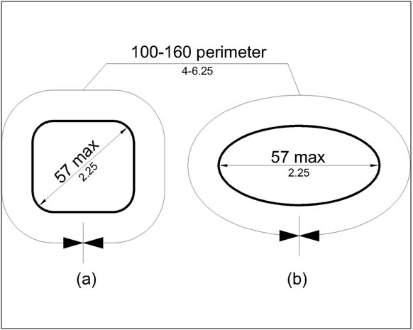
R409.8 Surfaces. Handrail gripping surfaces and any surfaces adjacent to them shall be free of sharp or abrasive elements and shall have rounded edges.
R409.9 Fittings. Handrails shall not rotate within their fittings. Where expansion joints are necessary for large spans of handrails, the expansion joint is permitted to rotate in its fitting.
R409.10 Handrail Extensions. Handrail gripping surfaces shall extend beyond and in the same direction of ramp runs and stair flights in accordance with R409.10. Extensions shall not be required for continuous handrails at the inside turn of switchback or dogleg ramps and stairways. In alterations where handrail extensions would reduce the clear width required for pedestrian access routes, handrail extensions shall not be required.
R409.10.1 Top and Bottom Extension at Ramps. Ramp handrails shall extend horizontally above the landing for 305 mm (1.0 ft) minimum beyond the top and bottom of ramp runs. Extensions shall return to a wall, guard, or the landing surface, or shall be continuous to the handrail of an adjacent ramp run.
Figure R409.10.1 Top and Bottom Extension at Ramps
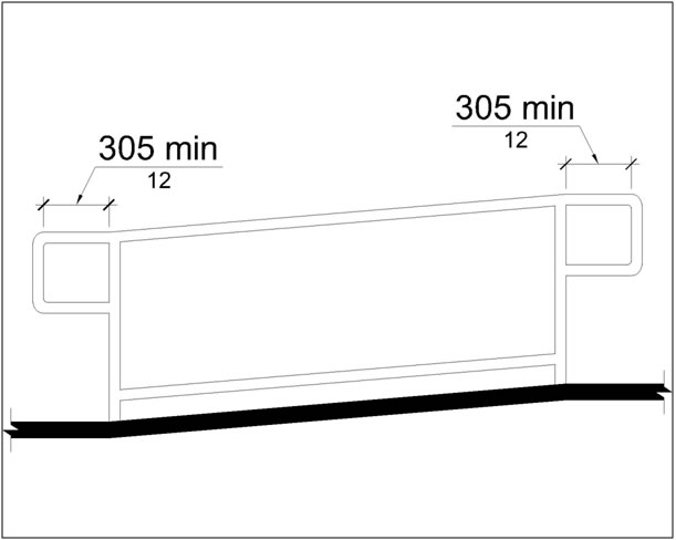
R409.10.2 Top Extension at Stairways. At the top of a stair flight, handrails shall extend horizontally above the landing for 305 mm (1.0 ft) minimum beginning directly above the first riser nosing. Extensions shall return to a wall, guard, or the landing surface, or shall be continuous to the handrail of an adjacent stair flight.
Figure R409.10.2 Top Extension at Stairways
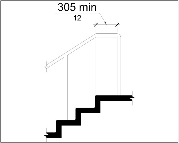
R409.10.3 Bottom Extension at Stairways. At the bottom of a stair flight, handrails shall extend at the slope of the stair flight for a horizontal distance at least equal to one tread depth beyond the last riser nosing. Extensions shall return to a wall, guard, or the landing surface, or shall be continuous to the handrail of an adjacent stair flight.
Figure R409.10.3 Bottom Extension at Stairways
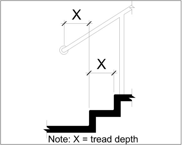
R410 Visual Characters on Signs
R410.1 General. Visual characters on signs shall comply with R410.
R410.2 Finish and Contrast. Characters and their background shall have a non-glare finish. Characters shall contrast with their background with either light characters on a dark background or dark characters on a light background.
Advisory R410.2.1 Finish and Contrast. Signs are more legible for pedestrians with low vision when characters contrast as much as possible with their background. Additional factors affecting the ease with which the text can be distinguished from its background include shadows cast by lighting sources, surface glare, and the uniformity of the text and its background colors and textures. |
R410.3 Case. Characters shall be uppercase or lowercase or a combination of both.
R410.4 Style. Characters shall be conventional in form. Characters shall not be italic, oblique, script, highly decorative, or of other unusual forms.
R410.5 Character Proportions. Characters shall be selected from fonts where the width of the uppercase letter "O" is 55 percent minimum and 110 percent maximum of the height of the uppercase letter "I".
R410.6 Character Height. Minimum character height shall comply with Table R410.2.5. Viewing distance shall be measured as the horizontal distance between the character and an obstruction preventing further approach towards the sign. Character height shall be based on the uppercase letter "I".
| R410.6 Visual Character Height | ||
|---|---|---|
Height to Finish Surface From Baseline of Character |
Horizontal Viewing Distance |
Minimum Character Height |
1.0 m (3.3 ft) to less than or equal to 1.8 m (5.8 ft)
|
Less than 1.8 m (6.0 ft) |
16 mm (0.625 in) |
1.8 m (6.0 ft) and greater |
16 mm (0.625 in), plus 3.2 mm (0.125 in) per 0.3 m (1.0 ft) of viewing distance above 1.8 m (6.0 ft) |
|
Greater than 1.8 m (5.8 ft) to less than or equal to 3.0 m (10.0 ft) |
Less than 4.6 m (15.0 ft) |
51 mm (2 in) |
4.6 m (15.0 ft) and greater |
51 mm (2 in), plus 3.2 mm (0.125 in) per 0.3 m (1.0 ft) of viewing distance above 4.6 m (15.0 ft) |
|
Greater than 3.0 m (10.0 ft)
|
Less than 6.4 m (21.0 ft) |
75 mm (3 in) |
6.4 m (21.0 ft) and greater |
75 mm (3 in), plus 3.2 mm (0.125 in) per 0.3 m (1.0 ft) of viewing distance above 6.4 m (21.0 ft) |
|
R410.7 Height from Finish Surface. Visual characters shall be 1.0 m (3.25 ft) minimum above the finish surface.
R410.8 Stroke Thickness. Stroke thickness of the uppercase letter "I" shall be 10 percent minimum and 30 percent maximum of the height of the character.
R410.9 Character Spacing. Character spacing shall be measured between the two closest points of adjacent characters, excluding word spaces. Spacing between individual characters shall be 10 percent minimum and 35 percent maximum of character height.
R410.10 Line Spacing. Spacing between the baselines of separate lines of characters within a message shall be 135 percent minimum and 170 percent maximum of the character height.
R411 International Symbol of Accessibility. The International Symbol of Accessibility shall comply with Figure R411. The symbol and its background shall have a non-glare finish. The symbol shall contrast with its background with either a light symbol on a dark background or a dark symbol on a light background.
Figure R411 International Symbol of Accessibility